Download
1 / 25
250 likes | 360 Vues
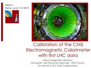
Design Requirements for the CMS ECAL. Specifications of the ECAL DCS. Detailed specifications of the ECAL Safety System. ECAL SS prototype - Test-beam results. Detector Control and Safety System for the Electromagnetic Calorimeter of CMS. Predrag Milenovic CMS Belgrade Group.

E N D
Design Requirements for the CMS ECAL Specifications of the ECAL DCS Detailed specifications of the ECAL Safety System ECAL SS prototype - Test-beam results Detector Control and Safety System for the Electromagnetic Calorimeter of CMS Predrag MilenovicCMS Belgrade Group
Large Hadron Collider CMS ATLAS ALICE LHC: 27 km Circum., ~100m underground CERN
Compact Muon Solenoid SUPERCONDUCTING COIL Silicon Microstrips Pixels CALORIMETERS ECAL HCAL Scintillating PbWO4 crystals Plastic scintillator/brass sandwich IRON YOKE TRACKER MUON ENDCAPS MUON BARREL Drift Tube Resistive Plate Cathode Strip Chambers (CSC) Chambers (DT) Resistive Plate Chambers (RPC) Chambers (RPC)
Physics goal - The discovery of the Higgs at the LHC The favourable channel for low mass Higgs search:H→γγ Design criteria: High energy (and angular) resolution: Barrel: Stochastic term (a): 2.7%, Constant term (b): 0.5%, Noise term (c): 150 – 220 MeV Hermetic, granular Compact, operated inside a 4T magnetic field. Challenging radiation environment with an integrated dose: 1013 neutrons/cm2 and 1 kGy at h = 0to 2×10¹⁴ neutrons/cm2 and 50 kGy at h = 2.6. Fast response for 40 MHz bunch crossing rate. ECAL design criteria
Choices, Constraints, Challenges • Crystals – PbWO4 • Short X0 and RM • Fast light output (80% in 25ns) • Low light yield • Temp. sensitivity – -2.2%/ OC • Photodetectors – APDs,VPTs • Gain – 50(10). • QE – 80%(15%) @ 420 nm • Temp. sensitivity – -2.4%/ OC • Constraints: • Very hostile radiation environment at LHC; • 4T solenoidal magnetic field of CMS; • Low room-temperature scintillation yield of PbWO4; • Temperature dependence of crystal light yield and APD response. • Need to stabilise crystal volume temperature to 0.1oC
Temperature Stability Issue All 0.25 m electronics runs at 2.5V. 0.45 A/channel 1 A/board Radiation hard regulator has a drop out voltage of 1.5V Total heat power dissipated in the whole calorimeter ~300 kW Crystal light yield decreases by 2.2%/oC & APD gain decreases by 2.3%/OC. Removing all excess heat is critical for the stable operation of the detector. Systems of crucial importance for the ECAL: Cooling system & Detector Slow Control System Detector Control System (DCS)
ECAL DCS Design Objectives: • Exact monitoring of the crystal and APD temperature stability (18.0oC ± 0.1oC) • Measurement of the air humidity in the supermodule • Safety system for automatic FE electronics disconnection (due to cooling problems, overheating of electronics, water leakage, over-voltage/over-current in FE) • Development of the control software (sensors, HV, LV, cooling, safety…) Foreseen Difficulties: Sensors ~100m away from the readout electronics, not accessible, large radiation dose present in ECAL DCS Subsystems (independent on the DAQ): • Precision Temperature Monitoring (PTM) • Humidity Monitoring (HM) Collaboration of research groups: ETHZ, Protvino and Belgrade • ECAL Safety System (ESS)
ECAL Safety System • Full system autonomy in all aspects; • Independent, continuous temp. monitoring of the ECAL VFE + FE environment in both ECAL SM + EE; Precision : 0.2 oC • Archiving of temp. data and system information for analysis of the detector status and ESS performance; • Reliable hardwired interlocks with ECAL HV and LV Power Supply systems; • External Alarm Interfaces with ECAL Cooling system, Water leakage detection system, as well as interfaces with general CMS DSS and LHC TCR; • Prompt reaction on any external alarm or critical change of temperature inside the ECAL by issuing, in a proper time sequence, Warnings and Alarms to: • 1. HV System Crates (hardwired interlocks), • 2. LV System Crates (hardwired interlocks), • 3. System Operator (soft PVSS Warning and Alarm messages); • Radiation tolerance in accordance with CMS radiation dose specifications; • Maximum possible level of robustness, reliability, safety and maintainability;
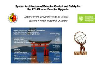
Schematic layout • Three interconnected system layers: • Temperature conversion and channel multiplexing - ESS FE Layer, • Data acquisition, data processing and interlock generating - ESS PLC Layer, • System monitoring and system control - ESS Soft Layer • Several external interfaces to: • ECAL Low Voltage, ECAL High Voltage and ECAL Cooling systems, • Input from Water leakage detection system • CMS Detector Safety System (DSS), • LHC Technical Control Room (TCR).
ESS Sensor Location Sensor 1 Screw hole Connector Sensor 2 In total288 + 64 SMD, 470 Ohms NTC thermistors (EPCOS) positioned in pairs at each measurement point ( “twin” sensors ). • 8 / EB SM • 8 / EE quadrant • Sensors to be calibrated to relative precision of 0.1 oC • with calibration setup developed by Belgrade group PSI irradiation: Sensors irradiated to 4-5 times EE dose – EPCOS sensors behaved perfectly
FE Electronic components RBFE ASIC • Resistant Bridge Front-End ASIC: IBM 0.25mm100 + 30% spares ordered (with LHC cryo group) • Bi-directional three-level programmable Internal Current Source (1mA, 10mA and 100mA), • Differential Amplifier, gain = 50 (adjustable), input range: -50mV – 50mV, output range: 0 - 5V, • Analog switches, 8 measurement modes of the chip, controlled by the Ck0, Ck1 and Ck2 bits, • Removes ASIC voltage offsets, thermocouple effects, power supply & ambient temperature dependencies Rad-tolerant Max4582: • TTL/CMOS compatible • Temperature Range • 0°C - 70°C • On-resistance • 150 Ohms at 5V • Off-leakage current • 1nA at 25°C • Low Distortion • Low crosstalk NTC 680 Ohms
FE Electronic components • Custom-made MUX + ‘RBFE’ test board, irradiated at PSI: • No problem, irradiated at ~ 106 x CMS balcony flux, and about 300 x CMS balcony dose • Tests in Belgrade: very satisfactory, could basically clock at 1 ms with 2x better resolution. • Has current generator at 500 μA • Need only (power, signal) 5V • Programmable Microcontroller test board, irradiated at PSI: • No problem, irradiated at ~ 106 x CMS balcony flux, and about 300 x CMS balcony dose • Purpose : • Control of MUXs and RBFE setup, Control of the communication (RS485), does ADC • Has watchdog timer, automatic RESET in case of blocking • Possibility to send remote RESET • Memory checksum sent: Control against SEU
FE Layer – ESS Unit Functional layout of ESS Unit in control of four ECAL Super Modules • Modular system - Independent ESS Units • Redundant readout - 4 SM or one Endcap • 12 in total units needed for (EE+EB+EB+EE) • Radiation tolerantcan sustain radiation levels orders of magnitudes higher than those expected on the CMS balconies • Redundant architecture - maximum reliability - minimum possible loss of temp. information from the inside of ECAL • Reliability analysis(for 4 designs) • This layout with 8 RBFEs/4SM has smallest prob. to loose large number of modules in case of component failure
ECAL Test Beam H4-Beamline, CERN • Real-life test of "almost" complete integrated system: • Readout: (PbWO4+APDs+VFE(100xFPPA or 50xMGPA)+FE(L1,3μs)) • Slow Control (DCS) and Monitoring: • LV, HV and Laser monitoring • Cooling and temperature stability • DCS subsystems: PTM, HM and ECAL SS • Online/Offline software • Validation of pre-calibration strategy (reproducibility and transferability to CMS in-situ) • Evaluation of effective detector performance (linearity, resolution, noise, stability) with new electronics design
ECAL Test-beam results with final electronics Position 1 mm Resolution(mm) Energy (GeV) Energy Resolution(%) Energy (GeV) 0.6% at 50 GeV. 0.85 mm at 50 GeV. Target calorimetry resolution achieved with new electronics design!
ECAL Test-beam results with final electronics We cannot calibrate every crystal with an electron beam. Obtain a first calibration point from component data: crystal light yield, APD & PA gain. Labo LY corr s = 4.05% Test Beam LY Test Beam LY – Labo LY corr Relative channel calibration can be obtained from Lab with a precision of 4 % In situ: Fast intercalibration based on f symmetry in energy flow 2% in few hours Energy/momentum of isolated electron from W→ en 0.5% in 2 months Absolute energy scale from Z → e+e-
ESS test-beam setup with SM0 RS 485 connection SM0
ESS test-beam results with SM0 ECAL SS (FE + Interface) PCB Calibration curve for one ESS sensor Noise distributions Noise dependence on RBFE position (ΔL ~ 40m) ~0.025°C ~0.04°C
ESS test-beam results – Example Cooling problems ! LV On ! LV On ! Cooling water temp. too high -> ESS interlock ! -> LV off ! ESS interlock ! Cooling problem solved ! Cooling problems ! System performance satisfactory !!! Oscillations of temperature of the air inside and outside of the SM0 are correlated!
Schematic layout RS485 RS485 • Three interconnected system layers: • Temperature conversion and channel multiplexing - ESS FE Layer, • Data acquisition, data processing and interlock generating - ESS PLC Layer, • System monitoring and system control - ESS Soft Layer • Several external interfaces to: • ECAL Low Voltage, ECAL High Voltage and ECAL Cooling systems, • Input from Water leakage detection system • CMS Detector Safety System (DSS), • LHC Technical Control Room (TCR).
ESS FE Layer • TSS FE is modular system made of ESS Units as independent modules, all identical • Each TSS unit has its own, independent and redundant power supply; • Each TSS unit provides redundant readout for four SM or one Endcap. There are 12 in total (1+5+5+1) units needed for (EE+EHB+EHB+EE) There will be at least 3-5 spare TSS units (about 16-24 spare entries in total); • TSS units can be interconnected in order to be controlled in parallel by the same PLC Control Signals --> possibility for parallel readout of several EB Super Modules and reduces the cabling between the Counting Room and the ESS Racks on the balconies; • Redundant architecture of the ESS readout unit : provide maximum reliability, so that, in the case of malfunction of any internal electronic components, the unit still works properly with minimum possible loss of temperature information from the inside of ECAL • All the electronic components of ESS FE Units have been shown (recent tests at PSI) that they can sustain radiation levels orders of magnitudes higher than those expected on the balconies...
FE Layer – ESS Rack Panel Layout of ECAL SS Unit Rack Layout of ECAL SS on CMS Blaconies