Tile Calorimeter Commissioning
240 likes | 258 Vues
This workshop overview discusses problems with FE electronics in a calorimeter, refurbishment progress, refurbishment recommendations, progress charts, and plans for the refurbishment project. It covers refurbishment techniques, tools, progress, and impact of refurbishments on the detector operation.

Tile Calorimeter Commissioning
E N D
Presentation Transcript
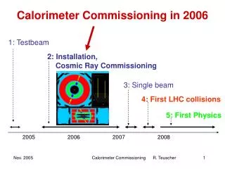
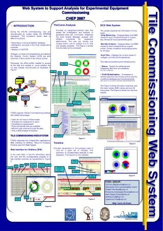
Tile Calorimeter Commissioning Claudio Santoni Université Blaise Pascal and IN2P3 On behalf of the TileCal Collaboration Physique ATLAS France Workshop Signosee, Pays Basque, France 10-12 September, 2007 2007
Overview • FE electronics • Low Voltage Power Supply • Cosmic runs • Cs Calibration • Laser Calibration • Conclusions Physique ATLAS France workshop, Seignosee 2007
FE electronics - problems All drawers were extensively tested and certified. Insertions finished end of June 2006 Significant problems discovered at end 2006 • Faulty connection to LVPS (Harting connector) • Unreliable connections to Mother Boards and Digitizer Board - Wiring not secure in connectors - Large Voltage drops in connectors - Problems with inter-board connectors • Data bus (Flex foils) connectors sensitive to pressure • HV flex-foils - HV breakdown across dirt on foils LVPS Digitizers Physique ATLAS France workshop, Seignosee 2007
FE electronics - refurbishment Intensive study at the beginning 2007 (Drawer task force) Fraction of compromised read-out channels (end of January) • No or strongly compromised physics 7% - HV trip inside the SD - Power problem inside the SD - BCD&CRC errors - ….. • Possible negative impact on physics 2% - Excessive noise - Stuck bits • No calibration 2% - Failing mezzanine - Damaged 3in1s • Inaccurate calibration 2% - E/Q far from one Failing rates increased with time (Expected 10% within 300 days) Impact of dead cells • Studied by ET-missing group • For 5% dead cells standard SUSY reference points are overwhelmed by QCD background Recommendations • Drawers should be fully refurbished • The development of improved tooling and access should have very high priority Physique ATLAS France workshop, Seignosee 2007
FE Refurbishment – The work • Check pins in Harting connectors • New screew terminals in MB and DB - Solder wires into these terminals - Connectors clamp onto pins on board • Collars or washer under flex-foil connectors for mechanical stability • Clean and insulate HV flex foils Harting connectors Digitizer connectors Signal flex-foil connectors Physique ATLAS France workshop, Seignosee 2007
FE Refurbishment - Progress Chart Integral Rate = 2.8 drawers/work week Rate bdg 171 = 2 drawers per day. Rate UX15 = 3 drawers per day. Refurbished drawers (blue/green = partial; red = full). Physique ATLAS France workshop, Seignosee 2007
FE after the partial refurbishment • No fully refurbished super-drawer has failed yet • Problem with the access to the SD’s. One need a space of 2m. Conflicts with the other detector operations • Plans till the end of the year in the pit • Refurbishing EBC SD’s (September) • Refurbishing EBA SD’s (October) • Insertion of the 29 LBC SD’s repaired in Bdg. 171 (December) • The refurbishing will continue in 2008 till the closing of the pit Physique ATLAS France workshop, Seignosee 2007
FE Refurbishment - New tools TOOLS TO WORK ON SCAFFOLDING WITH 3m ACCESS FOR IN-SITU REPARATION • Full length superdrawer extraction. • Superdrawer rotation once extracted to access both high voltage and readout electronics. • Maximize transparency to allow good access to drawer electronics PROTOTYPE WILL BE TESTED AT THE MIDDLE OF SEPTEMBER Possibility to extract the EB SD’s from the back Round frame supporting the tool Platform 0.6 m wide Physique ATLAS France workshop, Seignosee 2007
LVPS Significant problems discovered at beginning 2006 • Lack of effective OVP on bricks. • Noise and ripple on output. Modifications of the PCBs began atbeginning of 2007 • Progress since then has been steady. 8 DC/DC converter bricks ELMB-MB Heat sink LVPS box Physique ATLAS France workshop, Seignosee 2007
LVPS – Progress Chart LVPS installation versus time Physique ATLAS France workshop, Seignosee 2007 10 10
LVPS after implementation Installation almost completed Requirements for modifications well met • Output voltage protection well implemented in both hardware and control software. • DC-DC converter circuit stable operation • Safe sequencing of voltages • Stable operation for most power supplies. • Still some failures due to cold soldering either at modifications or manufacturer. Physique ATLAS France workshop, Seignosee 2007
Cosmics Runs – Setup and Trigger • The three partitions EBA, LBA and LBC are read out through final ROD-ROS system • Applied optimal filter in the ROD • Twelve modules at the top and twelve at • the botton of each of the three partitions • are used to trigger on cosmic muons • Each LB (EB) module provides eight (five) • trigger towers, constructed out of three • consecutive calorimeter readout cells • along the radial direction • Events are accepted if both a top and a • bottom tower show a significant signal • over noise in coincidence Physique ATLAS France workshop, Seignosee 2007
Cosmics Runs – Detector Monitoring NOISE DETECTION 10-15% of towers masked as noisy but vast majority related to cosmic boards or cabling, not Tile Physique ATLAS France workshop, Seignosee 2007
Cosmics Runs – DCS • ELEMENTS • LVPS • 200V PS • Auxillary Board • HV • Wiener crates • The HV DCS System was debugged starting from the M3 monitoring usage Physique ATLAS France workshop, Seignosee 2007
Cosmics Runs – Event Disply The passage of a cosmic muon through the Lar and TileCle. The size of yellow boxes, representing hit cells, is proportional to the deposited energy Combined cosmic event ATLANTIS display Physique ATLAS France workshop, Seignosee 2007
Cosmic runs – Monitoring Towers The distribution of the energy in the most energetic tower shows a clear muon signal Physique ATLAS France workshop, Seignosee 2007
Cosmics Runs – Reconstructed tracks The cosinus of the angle between the track and the vertical axis Physique ATLAS France workshop, Seignosee 2007
Cs Calibration All cells equalized using a 137Cs source • HV adjusted to have the same mean amplitude of tiles in cell ( 3.7%) • The TileCal energy scale of a cell is determined using electrons of a fixed • energy and incident angle • 12% of modules have been exposed to • electron beams • Only side cells calibrated • Cs equalization allows to use the measured • value for all the cells Physique ATLAS France workshop, Seignosee 2007
Cs Calibration • HYDRAULIC EQUIPMENT • Fully connected • Equipment commissioning in progress (LBA: finished, LBC: finished, EBA: finished, EBC: ready to start water tests) SENSORS ABD ELECTRONICS CONTROL BOARDS • LBA, LBC, EBA: finished. EBC: installed, to be tested DUMMY SOURCE RUNS • LBA, LBC, EBA: regular runs to verify functionality Cs run control GUI Hydraulicequipment in UX15 Physique ATLAS France workshop, Seignosee 2007
Laser Calibration • Monitoring • A fast on-line control of the working of the PMTs and the associated FE electronics • A measurement of the time drift of the PMT relative gains • A measurement of the linearity of each PMT • A correction of the saturated channels • Determine the timing of TileCal Laser installed in USA15 Laser system already sending light to front-end and used for timing adjustment Front-end Laser crate Laser pump Patch panel Physique ATLAS France workshop, Seignosee 2007 Timing of the channels of a SD
Set up: Laser Box (vertically in the rack) • Laser light amplitude monitored by 4 PDs. • Timing monitored by 2 PMs • Stability of PD’s and of the associated electronics monitored by an Americium source () (absolute stability) and a Charge injection system (linearity) Physique ATLAS France workshop, Seignosee 2007
Laser Stand-alone Commissioning • COMPLETED • PERFORMANCE OF MONITORS (PD MAINLY) FITTING SPECIFICATIOS • Stability of detectors (even though corrections are possible). • -A precision of 0.1% easily reached with a small statistics. PD’s response to versus time Physique ATLAS France workshop, Seignosee 2007
Laser Commissioning – Next Step CHANGE OF COMMERCIAL ADC BY A NEW ONE -Specially designed to fit timing constraints INTEGRATION WITH TDAQ AND ATHENA DEAD LINE: END OF NOVEMBER Physique ATLAS France workshop, Seignosee 2007
Conclusions • All the services of the 4 detector partitions are complete, last connections of EBC fingers now happening • Refurbishment process working steadily. • LVPS installation accomplishing deadlines. • Detector integration growing up • Calibration with Cesium on track. • Laser commissioning and integration started Physique ATLAS France workshop, Seignosee 2007