Download
1 / 29
290 likes | 493 Vues
The Detector Control Power System of the Monitored Drift Tubes of the ATLAS Experiment. Theodoros Alexopoulos NTU Athens. TWEPP08 September 17, 2008 Naxos, Greece. Outline. Detector Control System (DCS). Introductory Remarks about DCS MDT in ATLAS Experiment Structure of DCS

E N D
The Detector Control Power System of the Monitored Drift Tubes of the ATLAS Experiment TheodorosAlexopoulos NTU Athens TWEPP08 September 17, 2008Naxos, Greece
Outline Detector Control System (DCS) • Introductory Remarks about DCS • MDT in ATLAS Experiment • Structure of DCS • Power Systemsfor MDT • Summary
DCS - Introduction • Detector Control Systems • Systems to control (via computers) the operation of a HEP experiment • Appeared in 1980’s • Increasing Complexity of the Experiments • Control of a large amount of parameters • Check of the smooth operation of the experiment • Characteristics • Operators don’t need to be sub-detector experts • Operation procedures become very easy • Automatic Error Recovery procedures can be implemented
Standard DCS Model (Client-Server Model) OPI Operator Interface OPI Operator Interface Clients LAN-ETHERNET Servers IOS Input/Output Server IOS Input/Output Server IOC Input/OutputCntrl IOC Input/Output Cntrl Controllers OPI: Operator Interface , IOC: Input/Output Controller, IOS: Input/Output Servers
What does DCS involve? Control, Configuration, Readout, Monitoring of Hardware devices (but not readout of event data) Monitoring of external systems (LHC, Safety, Electrical, Gas, etc) Communication with DAQ Logging of data, status, storage in database Implementation of Finite State Machine behavior Partitioning
DCS Architecture External systems central control subDet 1 subDet 2 subDet 3 Control Units subSys 1 subSys 2 Driver 1 Driver 2 Device Units Device 1
Typical DCS Architecture (physical subsystem layout) OPI laptop Remote Users Remote Workstations OPI terminal OPI terminal WAN SCADA WAN LHC Safety Server DB server OPI OPI terminal Local Workstations Oracle bridge bridge LAN-ETHERNET I/O Servers distributed in Experimental area OPC IOS Beam Server caen-hv elmb I/OControllers Analog/Digital channels, Fieldbuses fieldbuses Beam-line Experiment Sub-Detectors & Experimental Equipment LHC data
Supervisory Control And Data Acquisition System: PVSS Commercial product PVSSII from ETM, Austria LHC wide decision • Can be distributed over many stations • Flexible and open architecture • Basic functions for automatisation • Standardized interface to the hardware • Application programming interfaces
What is OPC? • OPC defines a standard to interface programs (SCADA, HMI) • and hardware devices in a control system. • OPC provides a multi-vendor interoperability. No more specific drivers needed for each client Application X Application Y Application X Application Y OPC Interface OPC Interface OPC Device A Device B OPC Server OPC Server Device A Device B • OPC (OLE for Process Control) is based on the MS object model COM/DCOM (Component Object Model). • OPC includes 3 interface specifications: • Data Access • Alarm and Event Handling • Historical Data Access
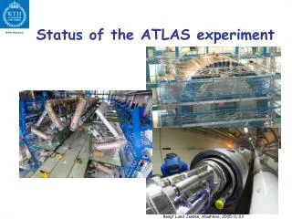
A Toroidal LHC ApparatuS LHC Experiments ATLAS Diameter: 25 m Length: 44 m Weight: 7 kT ~100 M electronic chs 1150 MDT chambers 354 384 Tubes 214 Tonnes 725 m3 Gas Volume 5520 m2 Chamber Area
ATLAS Inner Detector Calorimeters Muons TRT Pixel LArg Tile SCT Trigger Precision TGC RPC MDT CSC 46m TRT: Transition Radiation Detector SCT: Silicon Central Tracker TGC: Thin Gap Chamber RPC: Resistive Pad Chamber MDT: Monitored Drift Tubes CSC: Cathode Strip Chamber 25m
Muon Spectrometer • Two Basic partsBarrel και EndCap: • Barrel: 3 cylinders(inner-middle-outer) • EndCap: 3 disks • Chambers: MDT, CSC, RPC, TGC 1150 MDT chambers 354 384 Tubes 214 Tones 725 m3 Gas Volume 5520 m3 Chamber Area
DCS Architecture in ATLAS WAN DSS Global Control Stations (GCS) LHC Magnet Operator Interface Data Viewer DCS_IS Alarm Status Web CERN Subdetector Control Stations (SCS) Pixel TRT CIC Tile SCT MDT TGC RPC CSC TDAQ LAr Local Control Stations (LCS) High/Low Voltage Rod Power Gas Alignment Temp B-field JTAG Front-End Systems
Finite States Machine (FSM) • Definition:A finite state machine (FSM) or finite state automaton or simply a state machine is a model of behavior composed of a finite number of states, transitions between those states and actions. Structure ofFSM: State & Status ← GCS: Overall control of the detector ATLAS Commands MDT ← SCS: Full local operation of sub-detector Barrel A Barrel C EndCap C EndCap A ← TTC Partitions → INNER MIDDLE OUTER ← Layers BMS1C14 BML1C01 ← Chambers
ATLAS Global Control Station CIC Pixel SCT TRT LAr Tile MDT TGC CSC RPC Sub-detector Control Station EMB-A EMB-B EMEC-A EMEC-C HEC FCAL DAQ DAQ Partition DDC HV-PS HV THERMO ROD FEC Local Control Station Q1 Q2 Q3 Q4 Geographic partition HV sector 1 HV sector 2 HV sector n Device Units Operator Interface Finite State Machine (FSM) Architecture • The FSM (part of the JCOP Framework) is the main tool for the implementation of the full control hierarchy in ATLAS DCS • It is envisaged that the shift operators will operate DCS ONLY through the Operator Interface (based on the FSM) and the PVSS alarm screen JCOP: Joint Controls Project
Shift Operator Detector Expert SCS 1 ... TTC TTC TTC 1 . 1 1 . 2 1 . N Another Detector Expert LCS LCS LCS 1 . 1 . 1 1 . 1 . 2 N . 1 . 2 Sub-sys Sub-sys 1 . 1 . 2 . 1 1 . 1 . 2 . 2 Dev Dev Dev Dev Dev Dev 1 2 3 4 5 N Operator InterfaceFSM (Partitioning) GCS ... SCS 2 SCS N TTC N . 1 LCS N . 1 . 1 ... Dev N - 1
STATE Operator Commands STATUS GCS Operator ... SCS 1 SCS 2 SCS N ... TTC TTC TTC TTC 1 . 1 1 . 2 1 . N N . 1 LCS LCS LCS LCS 1 . 1 . 1 1 . 1 . 2 N . 1 . 1 N . 1 . 2 Sub-sys Sub-sys 1 . 1 . 2 . 1 1 . 1 . 2 . 2 ... Dev Dev Dev Dev Dev Dev Dev 1 2 3 4 5 N - 1 N Operator InterfaceFSM (STATE and STATUS) Messages via a double Information Path – STATE & STATUS • STATEdefines the operational mode of the system (ON, OFF, etc) • STATUS defines how well the system is working (OK, WARNING, ALARM, FATAL) • Two parallel information paths. E.g. HV system is in RAMPING_UP state (which takes several minutes) and an error triggers. The error is propagated through the STATUS while keeping the same STATE
CAEN Power Supplies modules Mainframe CAEN SY1527 Branch Controllers A1676 Crates Boards LV: A3025 & A3016 HV: A3540P
Structure of MDT PS Experiment Area Control Bus Eltx Room Control Logic Easy Module Power Line Branch Controller SY1527 System mainframe Control Logic P. Service Line Easy Module 64 Crates Power Fail Use Interrupt 48V Power Source 48V Power Source 48V Backup Battery
PS OPC server SY1527 • Run a single OPC server on PS1 pc (scattered system) • PS2 Barrel System • PS3 EndCap System PS1 OPC server OPC Client OPC Client OPC Client EM EM EM PS2 PS3 CSC
PVSS datapoints • Datapoints that correspond to hardware modules (channels, boards, crates, branch controllers, mainframe) • Datapoints that correspond to the chambers • Internal datapoints • for the FSM • for the OPC Server (communication with hardware) • for the RDB manager (archiving of datapoint elements) Alarms are activated for the datapoints and their elements
FSM trees • One FSM tree is implemented for each partition • Hierarchy is set for the parts of the system (nodes and their children) • Commands and states propagate correctly
Barrel • All chambers are incorporated in the system having LV modules • HV modules for all chambers in all sectors
Endcaps • Both Big Wheels and Small Wheels (one for each side) are incorporated to the system having both LV and HV modules
Summary • ATLAS PS MDT DCS is a Robust System • Is being used… • Delivered & Tested on Time Members of ATLAS NTU-Athens DCS group: Ex-members Alexopoulos, T. Argyropoulos, E. Gazis, M. Bachtis, A. Iliopoulos E. Mountricha, C. Tsarouchas, G. Tsipolitis