Download
1 / 44
490 likes | 1k Vues
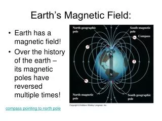
Physics 1. Magnetic field. Ing. Jaroslav J í ra , CSc. Magnetic Field. A magnetic field is a vector field that describes the magnetic influence of electric charges in relative motion and magnetized materials.

E N D
Physics1 Magneticfield Ing. Jaroslav Jíra, CSc.
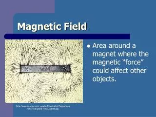
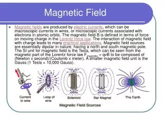
MagneticField A magnetic field is a vector field that describes the magnetic influence of electric charges in relative motion and magnetized materials. Magnetic fields are produced by electric currents, which can be macroscopic currents in wires, or microscopic currents associated with electrons in atomic orbits.
MagneticField, Definitionof If we place a test chargeq in theelectric and magneticfield, theforceacting on thechargewillhavetwocomponents. Electric force, whichdependsonly on theelectricfieldand is independent on themotionofthecharge. Theelectricforceisalsostraightforward. Magneticforce, whichdepends on themagneticfieldand on thevelocityofthecharge. Themagneticforceisalsoattherightangleswiththevelocity. To beable to describethemagneticforce, let usdefinethemagnetic induction. The unit ofisTesla. 1T= = Older, but still frequently used unit is Gauss; 1T= 10 000 G Theelectromagneticforceacting on thechargeqiscalledLorentzforceand canbewritten as
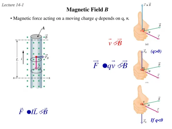
MagneticField, Definitionof e =q = q ( e Since the magnetic force is always at right angles with the direction of motion, then the work done on the particle is always zero. This means that the static magnetic field cannot change the kinetic energy of the particle, it can only change the direction of motion. How to determine the direction of magnetic force ? We can use either a right hand rule or a screw rule.
Direction of MagneticForce Right hand rule Screw rule = q ( If we are looking for the direction of a vector resulting from a vector product, it is obvious that the resulting vector is perpendicular to the plane where the vectors in product are positioned. Screw rule – if we rotate a right handed screw in the direction from the first vector to the second one by the shortest way, the screw will move in the direction of resulting vector.
MagneticField Lines Similarities to electric lines A line drawn tangent to a field line is the direction of the at that point. The density of field lines still represent the strength of the field Differences The magnetic field lines do not start and do not terminate on anything. They form closedloops. There is no magnetic analog ofelectriccharge. They are not perpendicular to the surface of the ferromagnetic material. They do not stop on the surface of ferromagnetic material Magneticdipole
Magnetic Flux Similarly to theelectricfieldwecandefinethemagnetic flux. A unit ofmagnetic flux isWeber[Wb]. As far as the magnetic field lines make closed loops and there is no magnetic charge, all field lines entering a closed surface must also leave it. We can define a Gauss’s law for the magnetic field. The magnetic flux through a closed surface equals to zero. This is also known as fourth Maxwell’s equation
MagneticForce on a Current Anelectriccurrentcanbeunderstood as a set ofmovingelectriccharges. Ifthemagneticfieldexerts a force on a movingcharge, thenitalsoexertsforce on a wirecarryingelectriccurrent. Let usdefine a differential element of a wireoflengthcarrying a steadycurrentI and placed in magneticfieldB. Thevectorindicatesthedirectionofthecurrentflow. I Theelementarymagneticforceis Fromthedefinitionofcurrent and velocitywecanwrite Theelementaryforceisthen Thetotalforceacting on a conductorofthelengthl:
Torque on a CurrentLoop We have a rectangularloopofheighth and lengthl in a uniformfield. Theloopcarries a currentI and itcanrotateaboutan axis x – x’. The orientation of the loop with respect to the is given by an angle α between and the vector of the normal to the loop. Using previously deduced formula we can see that the forces due to arms 1-2 and 3-4 are equal in magnitude and in opposite directions so they compensate each other – no net force. They also have the same line of action so there is no net torque.
Torque on a CurrentLoop Forces 41and 23have the same magnitude, opposite directions and they do not act along the same line, so there is no net force but they produce a torqueτm. where S= l is the area of the loop. We can now define a magnetic dipole momentof the loop:
Torque on a CurrentLoop Theformulaforthetorquecanbefurtherrewritten in thescalar and vectorform: We willassumethatthemagneticpotentialenergyUiszerowhen and are atrightangles (α=90°). Thepotentialenergyisequal to workW to rotatethedipolefromzeroposition to α. In vectorform Thisrelationisequivalent to theenergyofelectricdipole
ChargedParticle in MagneticField We willexaminenowwhathappenswhen a positivelychargedparticle (Q) enters a magneticfieldwithinitialvelocityperpendicular to the. y Q x Let usassumefortheinitialtimet=0 R According to theLorentzforce and Newton’s laws Since the and have only x and y components, we can simply decompose to x and y components. After the time integration we obtain
ChargedParticle in MagneticField For the magnitudes of velocity we can write This is an equation of a circle with radius R shifted on the y axis by yc. The period of revolution and frequency called cyclotron frequency can be expressed as Example: for an electron entering the field B= 0.1T with velocity v=104 m/s we have
Ampere’s Law An experiment with iron sawdust placed on a piece of paper around a wire carrying electric current perpendicular to the paper shows us that the force lines of magnetic field are circular with the center at the position of the wire. Another experiments found that the magnetic induction is directly proportional to the current I flowing through the wire and inversely proportional to the distance r from the wire. The constant of proportionality was defined as where μ0 is permeability of vacuum. The complete relation for the magnetic induction around the wire is
Ampere’s Law The previously found formula is valid only for the symmetrical circular arrangement. The Ampere’s law describes more general situation. Let us consider any closed path around the conductor. Let us determine the length integral We can see from the figure Using the known formula for B. So the Ampere’s law is Itisalsoknown as thefirst Maxwell equation
Biot-Savart Law The Ampere’s law could become difficult to apply in case of more complicated shapes of the wire. For these cases we have a magnetic equivalent of Coulomb’s law named Biot-Savart law. We will examine the magnetic induction at the point P around the wire carrying the current I. The contribution d of the infinitesimal element d is P α d 0 or where 0is a unit vector in the direction of and r=. The magnitude of dcan be expressed by To be able to determine the magnetic induction at P due to the whole wire, we have to integrate along the entire length l.
Application of Biot-Savart Law – long straight wire Determine the magnitude of at a distance R from the center of a long cylindrical wire carrying a current I. R r 0 -l
Application of Biot-Savart Law – circular wire I Determine the magnitude of on the axis of circular loop of radius R carrying a current I. dl dBx d R dφ R P dBz Vertical component dBx is compensated by the element on the opposite side of the ring, so only horizontal component dBz=dBsinΘcan be taken into account.
Application of Biot-Savart Law – circular wire Wefoundtheformulaforthe magnitude ofmagneticinduction. Ifwerealizethatthe sin Θcanbeexpressed as wecanrewritetheresult A graphforI= 1A, R= 5cm Important points and limits
Magnetic Force Between Wires The magnetic field of an infinitely long straight wire carrying I1 can be obtained by applying Ampere's law. I 1 A force exerted on the wire with I2 can be obtained as the Lorentz force. Taking into account that and are always perpendicular to each other, we can simplify to the relation of the force on length L. We can see by the screw rule or right hand rule that parallel current causes attractive force and antiparallel current causes repulsive force.
Magnetic Force Between Wires The attraction between two long parallel wires is used to define the current 1 Ampere. If we have two parallel wires 1 meter apart and the currents I1 and I2 are equal and of the same direction, then the current causing the attractive force F= 210-7 N/m is defined to be 1 Ampere. The magnetic force and knowlegde of it is very important in the power circuit design, especially for the cable installation and fixation. Let us suppose, that there is a device powered by two DC cables (plus and minus) and in case of short circuit the current flowing through cables would be 30 kA. If the cables are installed parallelly 5 cm apart, then the repulsive force between them would be 3600 N per one meter of length!!
ElectromagneticInduction Let us consider a conductor (a bar) placed in a uniformmagnetic field . Ifwe set theconductor in motionwithvelocityperpendicular to itsownlength and to the, charged particles in theconductorwillexperiencetheLorentzforce Thisforcepushespositive charges up and negative chargesdown. Electronsbegin to collectatthebottom part oftheconductorleavingtheupper part positive. Thischargeaccumulationgeneratesanelectricfieldwhichacts in theoppositedirection by itsforce. Thechargeaccumulationcontinuesuntil a balance betweenelectrostatic and magneticforcesisestablished. Theelectricfieldisthengiven by
ElectromagneticInduction Themovingconductive bar slideswiththevelocityalong a U-shapedconductorwithresistorR. Due to thegeneratedelectricfieldthecurrentIisestablishedthroughtheR. Thecurrentlowerestheaccumulatedchargewhilethemagneticforceaccumulatesanotherchargeattheendsifthemotionismaintained. Theforceexerted by themagneticfieldon theconductoris Anexternalforcemaintainingthemotionmusthavethesame magnitude and oppositedirection The distance traveled by theconductor in timedtis Theelementaryworkdone by theexternalforceis
ElectromagneticInduction – Faraday’s Law TheproductIˑdtrepresentsanelementarychargedq, so a d Theinducedelectromotiveforceis c b Whentheconductorismoving to theright, the area ofa-b-c-dincreases by Thechange in magnetic flux isthen Theinducedemfisgiven by The last term formstheFaraday’s law
Magnetic Induction – Faraday’s Law We could see in the previous that the magnetic force mcaused by the induced electric current was in the opposite direction than the force ext causing the motion. This is the principle of the Lenz’s law stating that the direction of induced current is such as to oppose the cause producing it. TheFaraday’s law can be also written in more general form. The emf can be written as and finally In combination with previous formulae This general form is also known as second Maxwell’s equation. The emf will be present regardless the cause of the magnetic flux change. The flux can be changed by moving a loop or a coil in the stationary magnetic field, by moving a permanent magnet, by changing the magnetic induction, by changing the shape of the loop etc.
Self Inductance Wehave a closedlooplcarrying a currentI. Magnetic flux ΦBthrough a surfaceSsurrounded by theloopisgiven by l S I Magneticinductionat a given point isaccording to the Biot-Savartlaw By combiningofthetwopreviousequationsweobtain Ifwe substitute wecanwrite ThequantityLiscalledself-inductance and itdepends on the geometry ofthewire and on the permeability oftheenvironment.
Self Inductance A unit oftheself-inductanceisHenry[H] and can be expressed as If the current passing through the loop varies in time then the magnetic flux varies as well and induces an emf, which opposes the original current. The value of emf induced in the loop is
Mutual Inductance Φ21 Now we have two loops placed near each other. The emfε2 induced in the loop2 is proportional to the rate of change of the Φ21, which is due to the current I1 in the loop 1. 2 If the loops are fixed in space then the Φ21 is proportional to the I1, which can be written as 1 I1 The proportionality constant M21 is called mutual inductance and its unit is also Henry [H]. Φ1 The emf induced in the second coil is Similar relation can be written for the situation when the loop 2 carries a current I2 and we want to express the emfε1 in the loop 1. The mutual inductance is symmetrical, so
MagneticFieldStrength and Magnetization Let usdiscussthesituationwhenthemagneticfieldispresent in anenvironmentdifferentfromvacuum, whichwascharacterized by the permeability ofvacuumμ0. As wehaveelementaryelectricdipoles,thereexistalsoelementarymagneticdipoles. We have a torus carrying a currentI0withiron coreand designed so thatthecorecouldberemoved. A hypotheticalsliceoutthecore has a magneticdipole moment as a sum ofallelementarydipoles in it. whereS·dlis a volumeoftheslice Thevectorofmagnetizationisdefined as Ifweremovethe iron core, themagneticinductionBinsidethe torus willsignificantlydecreaseforthesamecurrentI0. Wewouldhave to increasethecurrent by anamountIM to compensatethe drop and to achievetheformer magnitude ofB.
MagneticFieldStrength and Magnetization WecanseethattheAmpere’s law is not valid in the previously written form for the materials with magnetization and it must be modified to For our torus it can be rewritten to [1] where N is the number of turns. Wealready know that the dipole moment magnitude is For the coil with N turns it is or Using the definition of M where the term in the brackets means number of turns associated with the slice dl.
MagneticFieldStrength and Magnetization The last equation can be simplified to Substituting into the equation [1] we obtain In more general form it is Here we can define the vector of magnetic field strength . Now we can write the Ampere’s law in more simple form valid also for magnetic materials.
Permeability of Materials As we have relations between permitivities for the electrostatic field, we have similar relations between permeabilities for the magnetic field. Permeability of a material can be expressed as where is μr is dimensionless relative permeability. The relationship between magnetic vectors can be written also as According to the relative permeability we can divide magnetic materials into three categories: Diamagnetics – (μr<1, slightly). They create weak magnetic field opposite to an externally applied magnetic field. Paramagnetics- (μr>1, slightly). They are weakly attracted to magnetic field. Magnetization disappears without external field. Ferromagnetics- (μr>>1). Strong magnetization, which retains even after turning the external field off. They can form permanent magnets.
Permeability of Materials Comparison between permeabilities of diamagnetics, paramagnetics, ferromagnetics and vacuum
Energy Stored in Magnetic Field Let us examine a simple circuit consisting of resistor R, inductor L, switch S and DC voltage source Vs. When we turn the switch on, the current I starts to rise gradually. The equation for the voltages is then Imax If we multiply both sides by I, we obtain The term VsI expresses the rate at which the source delivers energy to the circuit. The term RI2 expresses the thermal energy in the resistor. The term LI represents the energy of the magnetic field of the coil.
Energy Stored in Magnetic Field The rate of change of the coil magnetic field energy Um can be written as This can be simplified as Byintegration we obtain The total magnetic energy stored in an inductor is Let usdeducetheformulaforUmwithmagneticfieldvectors. Wehave a straightwirecarryingthecurrentI and arounditwechosecircularflux tubewithcrosssectionS. Weknowthat S so
Energy Stored in Magnetic Field Theamountof flux enclosed by the tube is where S Themagneticfieldenergyenclosed in theelementaryvolumedVis UsingtheAmpere’s law we obtain Realizing that we obtain We can now define energy volume density
Summary – what we have learnt Lorentz force Gauss’s law for magnetism Ampere’s law Biot-Savart law Relations between magnetic induction, magnetic field strength and magnetization Faraday’s law Energy stored in an inductor Energy density of magnetic field
Application of Ampere’s Law – field inside and around a wire A long straight cylindrical wire of radius R carries a current I uniformly distributed in the cross section area. Determine the magnetic field strength H inside (r<R) and outside (r>R) the wire. a) r>R, we can use Ampere’s law We can simplify it for concentric arrangement b) r<R, inside the wire we are not surrounding the entire current I, but only a part of it I’, which will be used in te Ampere’s law
Application of Ampere’s Law – field inside and around a wire We have found relations for the magnetic field strength inside and outside the wire. r<R r>R H 0 r R
Example – Solenoid Determinethemagneticinductioninside very long solenoid ofcrosssectional area S, lengthl, numberofturnsNcarryingcurrentI. Determinealsorelationforitsselfinductance. Wewill use Ampere’s law. S The magnetic field outside long solenoid can be considered zero. Integral a-b is then zero. The is perpendicular to the on sections b-c and a-d, so the integrals are also zero. The entire integral reduces to The total current enclosed by the loop is NI because the loop encloses N turns with current I each. The field inside is homogeneous.
Example – Solenoid We already know the relation for magnetic flux In case of a coil we have to count magnetic flux through all turns For the constant B we can write so Substituting expression for B The self inductance of solenoid is Example: N=100, d= 1 cm, l= 20 cm Air core of the solenoid: L= 4.9 μH, Metal core (μr= 4000) of the solenoid: L= 19.7 mH
Example – Square Loop Calculate the magnetic induction B in the middle of a square loop carrying a current I= 30 A. Side of the loop a= 10 cm. We will divide the loop into eight parts of length a/2. Contribution to the total B of one such part will be B’. Due to the symmetry are contributions of each part in the middle of the square identical in magnitude and direction. Elementary contribution of the element is r α a/2 We will use substitutions
Example – Square Loop Due to the substitution we obtain Contribution of one a/2 part is The total magnetic induction is Numerical result for given values I=30 A, a= 10 cm