Download
1 / 20
200 likes | 349 Vues
Conformal Inkjet Direct Write on Aerospace Components. Industrial Doctorate Centre and BAE Systems Mau Yuen Chan Prof. Alan Champneys Dr. Jagjit Sidhu Dr. Paul Warr. This Presentation. What is direct w rite (DW)? Differences in method to traditional lithography Benefits of DW?

E N D
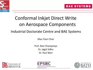
Conformal Inkjet Direct Write on Aerospace Components Industrial Doctorate Centre and BAE Systems Mau Yuen Chan Prof. Alan Champneys Dr. Jagjit Sidhu Dr. Paul Warr
This Presentation • What is direct write (DW)? • Differences in method to traditional lithography • Benefits of DW? • What advantages it brings • The challenges faced during the study • The DW system
Direct Write • A freeform patterning and deposition technique • Completes patterning and deposition simultaneously • Encompasses different deposition techniques • Droplet • Laser • Flow • Tip • No single ‘perfect’ technique • Innovative applications
Comparison to Convention • Lithography • Requires the use of masks • Large material wastage • Changes to designs costly • Etch step limits substrate material type • Substrates must be relatively planar • High capital cost • Direct Write • Freeform patterning • Low material wastage • Mass customisation • Variety of substrate materials possible • Substrates can be non-planar • Lower capital costs
Benefits for • Benefits: • Higher material efficiency • Mass customisation • Increased design freedom • Integrated functionality • COPE Project • Replacing electronic wiring with DW solution
The Helmet Shell • Aerospace Helmet used by pilots • Recognised as the most advanced helmet in the world • Undergoes further development to keep competitiveness • Even during the project study • Features: • Complex concave Shape • Carbon fibre substrate • Head tracking system; composed of LEDs and flexible connectors for wiring
The DW Process Design Execution Evaluation
Inks and substrates Electroplating Multi-discipline Mechatronics Physical Chemistry Printing system Multi-layers Electrical Engineering Mechanical Engineering Computer Science Control Systems Electrochemistry Post-processing Thermal Science & Physical Chemistry DW printed component Business
MasterCam® • The ‘creative brain’ • MasterCam is a CAD/CAM design software • Originally a software program for milling applications • Used to manipulate CAD models and design DW tracks • Output: Movement scripts for the motion controller
5-axis Motion Controller • The ‘arm’ • A motion control robot with five degrees of freedom giving it a large work envelop • All tools mounted onto working face • Required mechanical integration • Precision controlled (0.001mm accuracy) 150µm 100µm 50µm
Inkjet Printer • The ‘pen’ • Single nozzle jetting device (MicroFab) • Inks used • Polymer dielectric ink • Silver conductive nanoparticle ink • Can jet many materials • May require post-processing to functionalise
Bluewave® System • UV energy delivery system • Required for curing polymer dielectric ink • Controllable and localised output • Curing regime affects silver behaviour
iCure™ System • Thermal spot delivery system for sintering • Delivers focussed broad-band optical energy • + Controlled thermal exposure • + Superior electrical properties than oven sintering • - Difficulty on thermally conductive substrates • - Inks needed to be modified to match process
Thermal Damage • 4-point bend test used to investigate possible thermal damage caused by iCure process • Sintering requires at least 2.0W of energy • Speeds kept constant • Failure modes: • Compression – Resin failure • Tension – Fibre pull out • Significant loss in mechanical stability at more intense exposures
Electroplating • Chosen as a method of improving electrical conductivity of DW tracks • Improvement to DW track conductivities (reaching ~50-70% bulk Cu) • Uses brush plating method to deposit copper • Several designs iterated: • Improvement to electrolyte flow • Higher current density • Lower surface damage to copper deposit • Be able to navigate around complex 3D structures • Automatic feed/extract system for fluid • Further improvements: • Use of local cathode ‘ring’ for local connection
Connector Tabs • Communications with the manufacturer • Requirements capturing • Resolving needs and expectations • Suitable for existing processes • Several designs created for manufacturer’s approval • Final design: Connector tab (c) • Soldered into place • Flexible
The DW Helmet • Aim: To replace chunky wiring in helmet shell with an integrated DW solution • DW elements successfully fabricated onto a section of the helmet shell • Hardware and DW elements were connected • DW elements passed preliminary round of aerospace durability tests
Conclusions • DW electronics demonstrated on an aerospace component • Developed a process that can fabricate DW electronics onto complex 3D structures • Future work: • Innovative full DW solutions to electronic applications • Repair work on damaged DW components • Scaling of process for full manufacturing environments
The End Questions?