Download
1 / 22
220 likes | 497 Vues
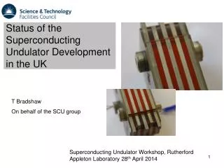
Status of the Superconducting Undulator Development in the UK. Superconducting Undulator Workshop, Rutherford Appleton Laboratory 28 th April 2014. T Bradshaw On behalf of the SCU group. Introduction. Outline of the current UK developments in Superconducting Undulator Technology

E N D
Status of the Superconducting Undulator Development in the UK Superconducting Undulator Workshop, Rutherford Appleton Laboratory 28th April 2014 T Bradshaw On behalf of the SCU group
Introduction • Outline of the current UK developments in Superconducting Undulator Technology • Start with a brief retrospective of the Helical Undulator • Planar undulator specification • Major concerns and how we are handling those concerns • Status • Many people have contributed to the developments RAL Technology Department on Harwell Campus ASTec at Daresbury Laboratory Diamond Light Source on Harwell Campus 2
+ - Helical Undulator Design principles have grown from the work on Helical Undulator for the International Linear Collider: Undulator Period 11.5 mm Field on Axis 0.86 T Peak field homogeneity <1% Winding bore >6mm Undulator Length 147 m Nominal current 215A Critical current ~270A Manufacturing tolerances winding concentricity 20µm winding tolerances 100µm straightness 100µm NbTi wire Cu:Sc ratio 0.9 Winding block 9 layers Ribbon 7 wire 3
Helical Undulator Fourier transform: Very pure sine wave Peak corresponds to 11.5mm period 5
Integration into Cryostat Magnet was integrated into cryostat and tested with current Field measurements in full cryostat were not attempted 6
Planar Undulator Development of a Superconducting Undulator for the Diamond Light Source 7
Major Concerns Everything really, this is a tough project …………. 8
Implementation The specification means that the tolerances on the manufacture are very tight (Ben Shepherd talk). Typically we are looking at ~10µm tolerances or of that order Magnetic length: 2 m Period : 15.5 mm Field on axis: 1.266 T -> K =1.8 Beam stay clear: 5.4 mm (Vert.) x 60 mm (Horiz.) rms phase error: < 3 degrees (target 2 degrees) Trajectory straightness: +/- 0.5 micron 9
Implementation • The end poles are stepped to ensure that the beam trajectory is straight. (Note that the trajectory can effect the phase error). • End windings have odd numbers of layers to make winding easier Coil layers = 5 7 9 11 ············ 2.35 4.8 3.83 4.8 ············ Pole heights =
Early Prototype tests Accurate translational stage Top Plate Carbon fibre rod supporting Hall probe Test Undulator 11
Prototype tests • Highest field magnetic measurement at 260A • Maximum magnet quench at 287A –need 407A • Issues with cracking on potting material • Peak fields on back of winding – need to improve spacing • Periodicity from sin fit at all currents is • 14.995mm +/-0.001mm at RT (10-100mA) • 14.963mm +/-0.001mm at 4K (10-260A) • Re-evaluation on how it is made 12
Test Pieces Section from straight, showing wires level with poles. Coil height measures 4.03 to 4.05mm. Winding trials and test pieces showing good winding technique: 13
Test Pieces Metrology is key to understanding the machining processes Profile of former has undergone many revisions to ease the winding process 14
Wire found to have voids: Wire Quality 15
Voltage Breakdown tests • Wire quality has been found to be an issue and details of winding has caused problems with electrical breakdown. • Looked at winding issues to reduce abrasion • Looked at insulation layer position and thickness • Looked at potting issues • Now achieved good results: 16
Forces Forces are enough to cause problems with alignment and positioning (Tim Hayler talk) 17
Interconnects Using crimps for the joints and interconnects – we have a large number of these so they need to be reliable and fully superconducting. Looking at finding a more compact crimp tool 18
Testing “Guillotine” approach to Hall probe carriage Arrangement made to minimise “crabbing” Concentric guide wheel and axel Eccentric guide wheel and axel 19 Carriage and rails GRP construction
Testing Formers sit on beam inside test cryostat We will be testing at 4K only 20
Summary • Large number of difficult technologies in this build – ticking off all of the technological challenges • Status: • Just about ready to build end magnet pieces • Prototype “straight” formers – have a drawing and a design • Building up test cryostat for magnetic measurements/training prior to build • Possible to build the magnet but difficult! Other talks will be dealing with the details of the technical challenges