Template for GNSS Service Performance Commitments
Template for GNSS Service Performance Commitments. 4 th ICG Meeting, Saint Petersburg, Russia 14-18 September 2009 Mr. Karl Kovach The Aerospace Corporation (Contractor Support to Global Positioning Systems Wing). Purpose and Overall Approach.

Template for GNSS Service Performance Commitments
E N D
Presentation Transcript
Template for GNSS ServicePerformance Commitments 4th ICG Meeting, Saint Petersburg, Russia 14-18 September 2009 Mr. Karl Kovach The Aerospace Corporation (Contractor Support to Global Positioning Systems Wing)
Purpose and Overall Approach • This briefing introduces draft example sections of the GNSS Providers’ Template for Performance Commitments • Overall approach • Adopt new ICG Principle at ICG4 (Sep 2009) • “Every GNSS provider should establish documented civil performance commitments to inform users about minimum levels of service” • In parallel, continue to develop a GNSS Providers’ Template for Performance Commitments • Supported by a common set of key terminology 2
Context • This briefing progresses an on-going theme • First introduced in “US WG-A Presentation on Compatibility and Interoperability”, 3rd ICG meeting, December 2008 (LtCol Harrington) • Further developed in “GNSS Service Performance Commitments…initial thoughts for consideration”, ICG Workshop on GNSS Interoperability, March 2009 (Mr. Steare) • Terminology introduced in “Key Definitions for GNSS Service Performance Commitments”, ICG WG-A meeting, July 2009 (Mr. Steare) • The presenter of this briefing was the lead author on the GPS Standard Positioning Service Performance Standard (SPS PS), September 2008
Template Plan 1. Develop common terminology 2. Develop list of parameters to be included in template • Continue review and refinement of existing list presented to ICG WG workshop in March 2009 • Distinguish between essential and desired parameters 3. Develop methodology for each parameter • Document the components to be addressed for each parameter (i.e., those conceptual contributions necessary to define the parameter) • Allocation of contributing errors (i.e. resolve potential discrepancies between space & control versus user segments) • Determine whether to use a preferred convention 4
Notional Timeline 2009 2010 Oct - Dec Oct - Dec Jan - Mar Apr - Jun Jul - Sep Jan - Mar Apr - Jun Jul - Sep • 1. Adopt Principle at ICG4 to encourage Performance Commitments ICG4 • 2. Publish a GNSS Providers’ Template for Performance Commitments • Common Terminology • List of Parameters • Methodologies 5
Proposed New ICG Principle Proposed New ICG Principle Every GNSS provider should establish documented civil performance commitments to inform users about minimum levels of service • Civil signal interoperability benefits users and receiver manufacturers • Better performance for receivers that use GPS and other signals together • More rapid and extensive adoption of highly interoperable signals • Interoperable signal-in-space (SIS) performance commitments allow a multi-GNSS receiver to manage contributions from each satellite SIS used to compute the positioning, navigation, and timing solution • Interoperable signals need interoperable SIS performance commitments • Consider interoperable signals from 3 GNSS-A satellites and 3 GNSS-B satellites • Without interoperable SIS performance commitments, the solution is just a guess
3 GNSS-A & 3 GNSS-B • Weighted Least Squares Position Solution • Measurement weights come from pseudorange domain accuracy • Need performance commitment for pseudorange domain accuracy from SIS • Receiver Autonomous Integrity Monitor (RAIM) • Probability of undetected faults comes from pseudorange domain integrity • Need performance commitment for pseudorange domain integrity from SIS
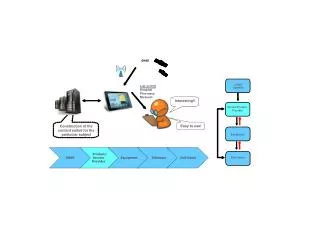
Line of Demarcation SPACE SEGMENT SIS INTERFACE CONTROL SEGMENT USER SEGMENT
At the Line of Demarcation • SIS interface is line of demarcation where GNSS service provider responsibilities end and receiver manufacturer/ user responsibilities begin • Take example of 3 GNSS-A satellites and 3 GNSS-B satellites • Multi-GNSS receiver manufacturer will decide how to integrate (interoperate with) this set of GNSS-A and GNSS-B satellites • Not under control of GNSS-A service provider or GNSS-B service provider • A GNSS service provider can only commit to the level of performance that its SIS interface will provide, and then operate the GNSS service to fulfill that commitment • Just as electricity service provider can only commit to the level of performance its interface will provide (voltage, frequency, etcetera) • Toaster manufacturer will decide how to toast the bread
Per Satellite SIS Basis • A “per satellite SIS” basis for performance commitments allows a GNSS receiver to manage contributions from each satellite SIS used to compute the positioning, navigation, and timing solution • True for a single-GNSS receiver faced with multiple blocks of satellites • True for a multi-GNSS receiver faced with different types of satellites • If service provider only publishes constellation-level commitments, then contributions from individual GNSS satellites are unclear • Does not support example of 3 GNSS-A satellites and 3 GNSS-B satellites GPS Lesson Learned #1: Using “per satellite SIS” as basis for performance commitments enables interoperability among multiple blocks of satellites GPS Lesson Learned #2: Using “per satellite SIS” establishes the least common denominator as minimum threshold for backwards compatibility
Performance Commitment Categories* • SIS Constellation Definition • SIS Coverage • SIS Accuracy • SIS Integrity • SIS Continuity • SIS Availability Combinations of “essential parameters” and/or user equipment assumptions allow for derived standards • *Chart from “GNSS Service Performance Commitments…initial thoughts for consideration”, March 2009
Performance Commitment Categories* • SIS Constellation Definition • SIS Coverage • SIS Accuracy • SIS Integrity • SIS Continuity • SIS Availability Combinations of “essential parameters” and/or user equipment assumptions allow for derived standards Radionavigation Systems Navigation Systems • *Chart from “GNSS Service Performance Commitments…initial thoughts for consideration”, March 2009
Performance Commitment Categories* • SIS Constellation Definition • SIS Coverage • SIS Accuracy • SIS Integrity • SIS Continuity • SIS Availability Combinations of “essential parameters” and/or user equipment assumptions allow for derived standards ~ Transmitter locations ~ Region(s) of SIS compliance • *Chart from “GNSS Service Performance Commitments…initial thoughts for consideration”, March 2009
Performance Commitment Categories* • SIS Constellation Definition • SIS Coverage • SIS Accuracy • SIS Integrity • SIS Continuity • SIS Availability Combinations of “essential parameters” and/or user equipment assumptions allow for derived standards See ICAO SARPs for example • *Chart from “GNSS Service Performance Commitments…initial thoughts for consideration”, March 2009
Example: Aviation Requirements Extracted from the ICAO SARPs Table 3.7.2.4-1 Signal-in-Space Performance Requirements NOTES.— 1. The 95th percentile values for GNSS position errors are those required for the intended operation at the lowest height above threshold (HAT), if applicable. Detailed requirements are specified in Appendix B and guidance material is given in Attachment D, 3.2. 2. The definition of the integrity requirement includes an alert limit against which the requirement can be assessed. 3. The accuracy and time-to-alert requirements include the nominal performance of a fault-free receiver. 4. Ranges of values are given for the continuity requirement for en-route, terminal, initial approach, NPA and departure operations, as this requirement is dependent upon several factors including the intended operation, traffic density, complexity of airspace and availability of alternative navigation aids. The lower value given is the minimum requirement for areas with low traffic density and airspace complexity. The higher value given is appropriate for areas with high traffic density and airspace complexity (see Attachment D, 3.4). 5. A range of values is given for the availability requirements as these requirements are dependent upon the operational need which is based upon several factors including the frequency of operations, weather environments, the size and duration of the outages, availability of alternate navigation aids, radar coverage, traffic density and reversionary operational procedures. The lower values given are the minimum availabilities for which a system is considered to be practical but are not adequate to replace non-GNSS navigation aids. For en-route navigation, the higher values given are adequate for GNSS to be the only navigation aid provided in an area. For approach and departure, the higher values given are based upon the availability requirements at airports with a large amount of traffic assuming that operations to or from multiple runways are affected but reversionary operational procedures ensure the safety of the operation (see Attachment D, 3.5).
Performance Commitment Categories* • SIS Constellation Definition • SIS Coverage • SIS Accuracy • SIS Integrity • SIS Continuity • SIS Availability Combinations of “essential parameters” and/or user equipment assumptions allow for derived standards Some detail More appropriate for a subgroup • *Chart from “GNSS Service Performance Commitments…initial thoughts for consideration”, March 2009
Performance Commitment: Pseudorange Accuracy Example Table III-x. SIS URE Accuracy Commitment
Assumed Common Characteristic: “Age of Data” (AOD) Parameter Upload Upload Upload Upload URE (Instantaneous), meters Time, hours
Assumed Common Characteristic: “Age of Data” (AOD) Methodology Upload Upload Upload Upload URE (Instantaneous), meters c. c. a. c. b. b. Time, hours b. b. c. • 95% over all AODs (i.e., over all time) • 95% at zero AOD (i.e., at time of predict for upload) • 95% at any AOD (e.g., at max AOD in this example)
Performance Commitment: Pseudorange Accuracy Example Table III-x. SIS URE Accuracy Commitment May want to omit, actually more appropriate as integrity For GPS, dd is essentially the data senescence “time out” limit
Way Ahead • Adopt the proposed ICG Principle • Add the Template activity to the WG-A workplan • Complete Performance Commitment Template by next year’s 5th ICG meeting • Identify POCs from each Provider • Leverage WG-A meetings to status progress during next year • Thoughts?
Way Ahead (Cont) Send feedback & suggestions to: Mr. Karl Kovach c/o GPS Wing (Aerospace) Karl.L.Kovach@aero.org
Example of a GPS Derived/Desired Performance Commitment: Position Accuracy • Position Accuracy depends on two factors: • Satellite-to-user geometry (i.e., the dilution of precision (DOPs)) • User Equivalent Range Error (UERE) • DOPs allocated between GPS SIS and Receivers • GPS SIS: constellation slots, number of healthy satellites • GPS Receivers: number of channels, mask angle, etc. • UERE allocated between GPS SIS and Receivers • GPS SIS: User Range Error (URE) • GPS Receivers: User Equipment Error (UEE) • GPS Performance Commitments cover GPS SIS performance allocations
Position Accuracy Allocation (Cont) • DOP Allocation: • Constellation Slots • Slot Occupancies • DOP Variations: • Number of Channels • Satellite Selection • Mask Angle • Vertical Aiding • UERE Allocation: • GPS SIS URE • UEE Variations: • Dual-/Single-Frequency • Troposphere Algorithm • Multipath Environment • Receiver Technology Position Accuracy