Download
1 / 72
740 likes | 966 Vues
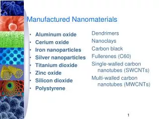
Learn about the intricate steps involved in IC fabrication, from silicon ingot slicing to transistor implantation, and the importance of photolithography. Dive into the detailed process of creating integrated circuits in a PC. Understand the layout design and fabrication rules for efficient IC production.

E N D
IC Manufactured Done by: Engineer Ahmad Haitham
The First Computers: BDE&ENIAC Vacuum Tube 1946 The Babbage Difference Engine (1832)
The Transistor Revolution First transistor Bell Labs, 1948 ECL 3-input Gate Motorola 1966 1st IC: Bipolar logic 1960’s
Intel 4004 and Pentium (IV) Ps 1971 1K transistors 1 KHz operation 2000 10M transistors 1 GHz operation
The Silicon Cylinder called Ingot (1 or 2 Meters in Length) Can be Sliced into Hundreds of Smaller Circular Pieces Called Wafers Each Wafer Yields Hundreds or Thousands of Integrated Circuits
Single die Wafer (20 – 30) cm diameter (0.35 – 1.25) mm thick
The surface is free of Scratches and imperfections
Die or IC Fabrication • There are 20 to 30 major steps. • Each step require five or more operations. • Hence, There are 100 to 200 distinct operations to produce a complete IC. • Today, IC chip may be up to 30mm on each edge and contains 100 million devices (Transistor, Diode, Resistor,…..etc)
Oxidation:High temperature exposure of silicon to oxygen to form SiO2. • Etching:Removal of undesired material with the use of chemical liquid or ionized gas etchant. • Diffusion:Doping process to form n-type or p-type material by high temperature exposure to donor or acceptor impurities
Ion Implementation:High-energy bombardment of silicon with donor or acceptor ions from certain accelerator • Chemical Vapor Deposition: Material such as metal or oxide are deposited out of a gaseous mixture. Metal can also be deposited using sputtering.
In the PC running certain software Draw a schematic that shows the layout of the geometric patterns that implement The transistors and interconnection
The patterns are converted to a set of masks, one for each major step in The fabrication process. Masksare glass plates with patterns specify the information that will be Printed to the IC in a given step
What is Photolithography?Process of transferring geometric shapes on a mask to the surface of a silicon wafer
Grow SiO2 Deposit polysilicon layer
Wafer is then coated with a polymer which is sensitive to ultraviolet light called a photoresist
There are two basic types of Photoresists, Positive and Negative. Positive Photoresists becomes soluble when exposed with UV light. Negative Photoresists becomes polymerized, and more difficult to dissolvewhen exposed with UV light.
mask, which will be typically be a chromium pattern on a glass plate • Ultraviolet light is then shone through the mask onto the photoresist • Positive photoresist
Thephotoresist is then washed by developer, The resist exposed with UV lightwill be dissolved
Etch the unwanted polysilicon. • Etching is the process where unwanted areas are removed by either dissolving them in a wet chemical solution (Wet Etching) or by reacting them with gases in a plasma to form volatile products (Dry Etching)
Remove the photoresist. • The polysilicon pattern is done.
Implant dopant ions through patterned openings in photoresist
Fabrication Process for DSM CMOS 1-Define Well areas and transistor regions. NMOS is diffused in a p-type well PMOS is diffused in a n-type well 2-Trenches are dug out of the silicon between the wells 3-Oxide is deposited in these stenches using the chemical vapor deposition process (CVD).
4-Define the gate region. Clean thermal oxide is grown in the transistor area by exposure to oxygen in a furnace.
5-Define the poly gate. Again a polycrystalline silicon layer is deposited by CVD 6-Undesired poly and oxide are removed by chemical etching or by plasma (Reactive gas)
7-Form source/drain regions. Ion implementation is used for the doping step.
8-Depositing silicide material to lower the resistance since because the source, drain and gate materials have relatively high resistance which may slow down the operation of the transistor..
Scalable rules (abstract dimensional unit , usually half of minimumfeature size) • The minimum feature size is L, the channel length of the MOSFET. • MOSIS SCMOS • http://www.mosis.org/Technical/Designrules/scmos/scmos-main.html#tech-codes • http://www.mosis.org/Technical/Layermaps/lm-scmos_scna.html
In general, there are three main classes of design rule specifications. These are • Minimum Width. Which is the smallest dimension permitted for any object in the layout drawing • Spacing. Which is the smallest distance permitted between the edges of two objects. • Surround. This apply to objects placed within larger objects (such as contacts). • Every layer has minimum width and minimum spacing value, while surround are specified as required.