Download
1 / 20
200 likes | 321 Vues
FPGA IRRADIATION @ NPTC-MGH (Part 1). Ray Mountain , Bin Gui , JC Wang, Marina Artuso Syracuse University. Outline. NPTC Facility & Irradiation FPGA Setup Results: Hard Errors, SEU, etc. (limited) Post-Mortem Analysis (Failure Mode) Operational Experience with FPGA Summary & Plans.

E N D
FPGA IRRADIATION @ NPTC-MGH (Part 1) Ray Mountain, Bin Gui, JC Wang, Marina Artuso Syracuse University
Outline • NPTC Facility & Irradiation • FPGA Setup • Results: Hard Errors, SEU, etc. (limited) • Post-Mortem Analysis (Failure Mode) • Operational Experience with FPGA • Summary & Plans THIS IS WORK IN PROGRESS ! LHCB Electronics Upgrade Meeting, 10/14/2010
NTPC Facility • Northeast Proton Therapy Facility @ MGH • Cancer facility, Mass General Hospital, Boston MA • Cyclotron: • 230 MeV p primary beam, Pb foil scatterer, collimating aperture • Gives 226 MeV (~2 x MIP) on target, essentially monochromatic, E bite <1% • Dosimetry: Calibration w/ ion chamber, Faraday cup, <10% absolute • Beam: 2.1e11 p/cm2s max, core 10 mm diam LHCB Electronics Upgrade Meeting, 10/14/2010
NPTC @ MGH FAR STATION Cyclotron NEAR STATION ~ 230 MeV Protons FPGA LHCB Electronics Upgrade Meeting, 10/14/2010
Cyclotron Louvain #00 LHCB Electronics Upgrade Meeting, 10/14/2010
Extraction and Beamline LHCB Electronics Upgrade Meeting, 10/14/2010
Patient Area (Gantry) SU VELO Meeting, 8/24/2010
Test Beamline LHCB Electronics Upgrade Meeting, 10/14/2010
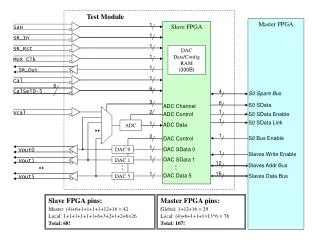
FPGA Setup (1) • FPGA used: Actel ProASIC3 A3PE1500-PQ208 • Our Setup: • FPGA on Eval PCB mounted in beamline, at 0 deg • AC Power on remote relay • Near station (PC, TNG DIO, XBD, etc.) • shielded, Borated PE (nth) • LabVIEW for comm and control • ActelLiberofor config • Far station (remote LT connected to Near PC) • Laser alignment, proton radiochromatography (proton “x-ray”), webcam LHCB Electronics Upgrade Meeting, 10/14/2010
FPGA Setup (2) Aperture Ø12.7 mm Ion Chamber FPGA Board p Beam Adjustable mechanics LHCB Electronics Upgrade Meeting, 10/14/2010
Near Station (Not manned during data-taking) B-PE shield Near PC Programmer B-PE shield LHCB Electronics Upgrade Meeting, 10/14/2010
Irradiation (1) • Irradiation • Dose up to 127 kRad(Si) • Fluence up to 3.9E9 p/cm2s @ 226.MeV • 226 MeV p = ~2 x MIP • General Procedure for data-taking • Configure (if needed) • Set CLK freq • Clear/Start • Irradiate (wait for fixed dose in a given run) • Read out results LHCB Electronics Upgrade Meeting, 10/14/2010
Irradiation (2) • Beam location • Centered on FPGA • Laser aligned, cross-checked with RCG image • Beam uniformity • Adjust thin foil scatterer, 19 mm diam aperture • About 8% over central 8 mm • FPGA die: 7.9 x 7.7 mm2 Proton radiochromatograph ~28 mm (pkg) ~8 mm (die) LHCB Electronics Upgrade Meeting, 10/14/2010
Results: Tests Planned • Basic Operation * • Monitor if FPGA is still alive • Cycle power occasionally • SEU * • Counter • Serial input to shift reg chain • Output from shift reg chain • Compare to original counter • If different, incr error count • (repeat @ various clk: 40, 120, 240 MHz) • RAM • Counter • W counter to ram (3x) • R ram • Compare to original counter, using TVS • If different, incr error count • (repeat @ various clk) • ROM • W rom with number (3x), using JTAG • R rom • Compare to original number, using TVS • If different, incr error count • (repeat @ various clk) • CFG * • (Re-)configure FPGA periodically • Verify configuration • Plan is to make all these measurements • For this first irradiation, those marked (*) were made • However SEU was a problematic case • Hard errors: full series LHCB Electronics Upgrade Meeting, 10/14/2010
Results: TID & Hard Errors • FPGA stopped responding somewhere >90 kRad • Specifically, failed during 2.9 min run with dose going from 89.9 to 127.0 kRad(Si), and fluence 3.92E+09 226.MeV p/cm2s • Firmware failure • No response to communciations asking for readout of counter • Plus configuration failure • Specifically, configuration failure code EXIT -24 (unstable vpump voltage levels), although vpump measured OK on PCB • Simple verification also failed • Tried to recover in situ • Power cycle FPGA, restart control program, power cycle PCs, repeated configs, recompilation, swap programmer, etc. • No success, so declared it dead • Our rough goal was: operational until 30 kRad • Expected rad levels were about 30 kRad/100.fb-1 • Note: other Actel A3P devices show adverse effects (propagation delay, frequency degradation) at doses >70 kRad LHCB Electronics Upgrade Meeting, 10/14/2010
Post-Mortem Analysis • Investigated a number of possibilities for FPGA failure mode • Timing, firmware • Hardware • Most likely culprit: low Vcc • 1.5 V DC core device power level, with limits 1.425–1.575 V • LDO Reg on Eval PCB generates 1.510 V • But at FPGA measured Vccranges from 1.398 V down to 1.315 V • All Vcc at FPGA are below lower operational limit • Corresponding Vcc on unirradiatedEval PCB is 1.5 V (good) • Caused by increased current draw in FPGA itself • Only traces between Reg and FPGA, no other resistive element • Estimate ~ 1 A draw (or more) • When FPGA removed from Eval PCB, all Vcc come back to 1.5 V • Increased Icc current sinking with dose is the behavior of RT54SX (antifuse device), spikes up >80 kRad • Due to: gate rupture, latch-up? • Tracing down physical cause (SEGR, SEL) • Recovery scheme? • Tried some different power routing: unstable Vcc after FPGA on for few seconds • Will try delivering independent completely off-board power • Annealing ? Will try this • Open to other suggestions LHCB Electronics Upgrade Meeting, 10/14/2010
Results: SEU Test • Problematic: • We had a large number of problems in Boston, mainly with timing and reproducibility (coding was a bit ambitious to begin) • Had to scale back tests and simplify code • Tried SEU test alone, no memory testing, no TVS • Retained 101010… input to shift register chain and bit-by-bit comparison, error counter, and communications blocks • Results: • Result is hard to interpret, saw small number of error counts for all runs (0 or 1 for most), but not increasing in the expected way • Possible that we have residual timing problem, perhaps at comparator (under study), so we are making no statements about SEU rate from this data at this time • Have performed a series of systematic studies to understand what we saw. Still under investigation, in contact with Actel engineering on this problem LHCB Electronics Upgrade Meeting, 10/14/2010
Operational Experience • Had a number of issues with this FPGA • Timing (old and new issues) • VHDL implementation suspect • Software interface, error reporting inadequate • Need to do more testing to get reliable behavior • Really have to dig into it, check all critical signal lines, etc. • We were too ambitious for a first irradiation test • Programmer problems • Many configuration failures in situ at NPTC (>30%); rare before and after at SU (~1%) • Recover by power cycle FPGA, rebooting PC, swapping programmers (repeatedly, or in combinations) • We had two programmers, both behaved badly • Maybe power was spiky at NTPC, or…? • Tremendous headache, caution about using FlashPRO3 in critical situation, it was very flaky • Reliability and reproducibility – some problems here…We had difficulties in reproducing detailed behavior of firmware, especially with regard to timing and synchronicity issues LHCB Electronics Upgrade Meeting, 10/14/2010
Timing Issues • Some systematic studies of timing • Use a small project, with counter, “firmware” delay (i.e., Actel module), and “writing” delay (VHDL code) • Set delay in code, measure delay on scope, get plot shown • Timing changes when recompile but not reconfigure • Known (offsets in this plot) • Timing delays using Actel module works, timing delays using VHDL block does not work at all • Simulates correctly, of course! • Syntactically-correct VHDL • Actel compiler didn’t flag this as an “error” for this FPGA • Really problematic, since Actel module is limited to ~7 ns delay • Still have not fully sorted all timing issues simulation device LHCB Electronics Upgrade Meeting, 10/14/2010
Conclusion & Plans • FPGA functioned normally under irradiation by 226 MeV p until dose reached 90–127 kRad(Si) • FPGA became unresponsive due to large current draw on the device (and consequently, a too-low Vcc) • SEU test results were difficult to interpret, due in part to timing issues and other problems found in situ. Similar for memory tests. Will revisit these tests (esp. with input from Actel engineering) • This FPGA seems to have a number of drawbacks, including timing and operational issues (and perhaps even VHDL implementation) • We are continuing to refine the diagnostics on dead FPGA, to understand the mechanism and a possible recovery scheme • Have established a baseline procedure for testing devices, including algorithm, communications, irradiation details, etc. • Plan is to settle issues found and follow up with another irradiation test LHCB Electronics Upgrade Meeting, 10/14/2010