Audio Signal Equalizer System for Enhanced Output Quality
Develop a basic equalizer system to manipulate audio signals by adjusting frequency bands, focusing on bass, midrange, and heights for improved output. Learn implementation, difficulties faced, results achieved, improvements needed, and project conclusion.

Audio Signal Equalizer System for Enhanced Output Quality
E N D
Presentation Transcript
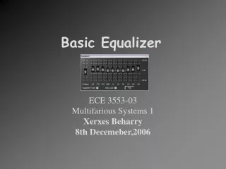
Basic Equalizer ECE 3553-03 Multifarious Systems 1 Xerxes Beharry 8th Decemeber,2006
Problem Statement • To create a system that was able to manipulate an audio signal so that the output is more pleasing to the air. This means adding bass, midrange or heights to an incoming signal. • The most basic of audio signals today allow an user to manipulate the audio signals, whether it be from one’s car stereo system or laptop. I attempted to create such a system, a basic equalizer paying special attention to the low and high frequency ranges because they are most easily recognizable
My Attempt • To mimic such a system capable of adjusting a few frequency bands • To put into practice what was learnt from the ECE 3551 labs and lectures.
System Modes of Operation • PF8 is used to toggle between increment and decrement • LED 4 on represents increment and off represents decrement • PF9 is used to adjust the low frequency band • PF10 is used to represents the high frequency band • If the max or min gain is reached for the low frequency band, it is indicated by LED5 • If the max or min gain is reached for the high frequency band, it is indicated by LED6
System Modes of Operation • LED 7 is an intensity indicator for the low frequency band • LED 8 is an intensity indicator for the high frequency band • PF11 toggles between the original signal being heard on 4 speakers, and the original signal heard on only 2 specific speakers and the manipulated signal on the other 2 speakers. This was done for comparison purposes.
Implementation • Any audio signal can be broken up into a band of frequencies. • Lower frequencies have deeper sounding tones as compared to high frequencies. • Higher frequencies have higher sounding tones.
Frequencies I concentrated on : • 0-170 Hz Used to adjust the bass • 600-3kHz Used to adjust the lower end of the midrange • 3k-12kHz Used to adjust the higher end of the midrange • 12k-16kHz Used to adjust the height
2nd Order IIR Band 1 Filter x[n] g2 gMaster 2nd Order IIR Band 2 Filter gi 2nd Order IIR Band i Filter gN 2nd Order IIR Band N Filter What I Used
Difficulties • Using different types of filters with different data types. • Obtaining proper filter coefficients from fdatool in MATLAB • Implementing filters that overlap each other for accurate sound quality
Difficulties • How to obtain a reasonable user adjustable gain for the different bands with the different types of filters used
Results • The results of my second attempt at creating the equalizer were much more desirable than the first. • A couple of mistakes that I made were attempting to manipulate too wide of a frequency band which actually defeats the purpose of the equalizer. • Not filtering the entire frequency range I believe is another reason for the results of my first attempt.
Improvements • Through trial an error it was realized that more bands that are available the more accurate the response that can be achieved from the equalizer. Ideally about 10 or 12 different bands would be sufficient to perform efficient equalizer functions on an input signal. • Having preset modes such as Rock, Hall, Soft Rock etc which may save the user time in trying to figure out the best combination of settings.
Conclusion • This project was considered a success as the result was as desired. It was very challenging but rewarding and although I have not created a full 12 band equalizer I believe that I now possess that knowledge necessary to do so given more time. I have learnt a lot about filters and their potential if implemented properly. • I have also learnt to use the very powerful MATLAB fdatool. It has broadened my horizons to see the many different ways to implement a filter that would produce similar results. I have also learnt that if you type in “why” in MATLAB it can relieve some stress as seen below:
Special Thanks • To: • Dr. V Kepuska • for taking the time to look at my first attempt. • Guogang Hua • for helping me out in the labs during the semester.
References • http://my.fit.edu/~vkepuska/ece3551/ • http://www.altera.com/support/examples/dsp/exm-dsp.html • Dr. Kepuska’s class slides.