Touchpad-Controlled Parametric Equalizer
This project aims to create a real-time audio filtering solution that provides independent control over filter parameters like center frequency, bandwidth, and gain. The design includes a pressure-sensitive touchpad for intuitive input control and a DSP-implemented algorithm for filter processing. The touchpad interface, positioning algorithm, and serial communication setup are detailed.

Touchpad-Controlled Parametric Equalizer
E N D
Presentation Transcript
Touchpad-ControlledParametric Equalizer ECE 445 Group #24 Anthony Mangognia Alexander Spektor Farsheed Hamidi-Toosi TA: Chad Carlson
Introduction • Goal: To create a real-time audio filtering solution for musicians and sound engineers • Goal: To provide independent control over filter parameters: center frequency, bandwidth, and gain • Goal: To create a geometrically-intuitive input device for the filter
Existing Alternatives • X-Band Equalizers • Sliders or knobs • Limited control • Takes time to adjust • Discrete frequency bands • Digital Parametric Equalizers • Pseudo-continuous frequency sweep • Cumbersome software-based control
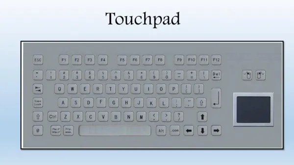
Design Overview • Input Device: Pressure-sensitive touchpad. • Horizontal position: center frequency • Vertical position: gain • Overall Pressure: bandwidth • Input-Filter Interface: RS-232 serial connection • Filter: DSP-implemented algorithm • Second-order IIR filter (based on Mitra-Regalia topology) • Filter coefficients update in real-time
Design Block Diagram Audio In DSP: Parametric Equalizer Filter Microcontroller: Positioning Algorithm & Touchpad DSP interface Audio Out Touchpad
1. Touchpad Process Pressure Sensor Voltage Differential Bias cancellation/Tuning Circuit 830x Amplifier PIC A/D
Touchpad • Four corner-mounted pressure sensors on height-adjustable shelves • Pressure sensor output voltage varies with finger position • Positioning algorithm • Surface much larger than typical commercially-available touchpads
Touchpad Design Touchpad Surface Sensor Mount Pressure Sensors Slide-in touchpad Bird’s Eye View Height-adjustable sensor mount Sensor Mount
Pressure Sensors • Honeywell 125PC30G1 • Pressure range: 0-30 psi • Sensitivity: 8.33mV/psi V- GND V+ +10 Amplifier
Touchpad Signal Amplification • Instrumentation Amplifier: AD622AN • Low-cost: $4.90 • Gain: 2-1000x, external resistor control • 56Ω 830x gain • Easy integration: wide power supply voltage gain (±2.6V-±15V) • Large gain Large bias voltage • Solved with 1MΩ pull-down resistors at inputs and 100k potentiometer (calibration)
2. Microcontroller-EnabledTouchpad DSP Interface Four sensor A/D Positioning Algorithm Serial Transmission
Analog to Digital Conversion • 8-bit A/D conversion for quicker calculations • 10-bit possible for PIC16F877A, but doubles number of bytes for mathematical operations • Decreases resolution to 256 points maximum • More than enough to simulate continuous operation • Read 8 values for each sensor and average • Functions as a digital LPF
Positioning Algorithm Sensor 1: V1 (0, Ymax) X2 = V2 Xmax / (V2 + V1) Sensor 2: V2 (Xmax, Ymax) Touchpad Surface Y1 = V1 Ymax / (V1 + V0) Y2 = V2 Ymax / (V2 + V3) (X,Y) – Finger Position Sensor 3: V3 (Xmax, 0) Sensor 0: V0 (0, 0) X1 = V3 Xmax / (V3 + V0)
Positioning Algorithm Sensor 1: V1 (0, Ymax) X2 Sensor 2: V2 (Xmax, Ymax) Touchpad Surface Y1 (Xavg,Yavg) – Average Y2 Sensor 3: V3 (Xmax, 0) Sensor 0: V0 (0, 0) X1
Positioning Algorithm Sensor 1: V1 (0, Ymax) Sensor 2: V2 (Xmax, Ymax) X’ = X1 (Ymax-Yavg) + X2 (Yavg) Touchpad Surface (X’,Y’) – Weighted Average Y’ = Y1 (Xmax-Xavg) + Y2 (Xavg) Sensor 3: V3 (Xmax, 0) Sensor 0: V0 (0, 0)
Data Sent to DSP • Three-byte start sequence: “230” x3 • Four sensor readings: S0, S1, S2, S3 • Two one-byte positioning words (x3) • One three-byte stop sequence: “232” x3 230 230 230 S0 S1 S2 S3 X X X Y Y Y 232 232 232
Serial Data Transmission • Data transmitted at 38400kbps • Default rate for DSP • Data Format • Sent over standard serial cable • DB-9 connector 1 START BIT 8 BIT WORD 1 STOP BIT
RS-232: Voltage Level Conversion • PIC output at TTL levels • ~ 0 - 5V • DSP input at RS-232 levels • ~ ±12V swing • Conversion with MAX232 line driver 38400kbps serial data at TTL from PIC MAX232 Line Driver 38400kpbs serial data at RS-232 to DSP
3. DSP: Audio Filtering Receive/Decode Data from Touchpad Update Filter Coefficients Apply Filter to Audio Input and Send to Speakers
Filter Design • Based on Mitra-Regalia second-order IIR • Design Equations: • β = – cos(ωc) • k = 10(GAIN/20 dB) • α = (1 – tan (BW/2) (1 + tan (BW/2) • Programmed in C for TI-54x fixed-point DSP A(z) = All-Pass Lattice Mitra-Regalia Topology
Src: Montana University Web site. http://www.coe.montana.edu/ee/rmaher/ECEN4002/lab4_020226.pdf
Design Challenges: Touchpad • Pressure sensor noise • Problem: 30mV peak-to-peak noise level • Solution: 8-point averaging filter after PIC A/D • PIC A/D crosstalk • Problem: Changes in one pressure sensor affected values read for other • Solution: Pull-down 0.1μF capacitors at A/D input pins • Serial communication pins • Problem: PICPC communication and PICDSP communication use different DB-9 transmit pins • Solution: Internal rewiring to accommodate both
Design Challenges: Filter • Filter type change • Problem: Original algorithm (Chamberlin) produced undesirable resonance frequencies • Solution: Switched to Mitra-Regalia topology • IIR Instability • Problem: Direct form two implementation caused overflow • Solution: Implemented lattice structure to reduce overflow • Quantization • Problem: Fixed-point quantization of coefficients • Solution: Lattice structure ensures pole-zero cancellation
Internal Component Test • Pressure Sensor + Amplifier • Unwanted signal oscillation: 60mV peak to peak • Due to conflicting RC networks • Too high for 1V sampling range • Solution: Removed analog smoothing filter
Finished Product Test • Amplitude test performed with oscilloscope • Input: 11 kHz Sine Wave, 200 mV peak-to-peak • Tests: gain = 2 and gain = .5 at 11kHz by measuring peak-to-peak voltage of output using the scope • Amplitude resolution is .24 dB from -6dB to 6dB • Exceeded design requirement which stated 2-3 dB amplitude resolution
Finished Product Test • Frequency tests performed with scope • Fix bandwidth, set gain = 2 • Inputs: Sine at set frequencies, Gaussian White Noise • Using FFT on scope, can see if frequencies boosted by 2x at desired center frequency • Proposed frequency resolution: 1 Hz (not necessary) • Total of 200 center frequencies possible, distributed them logarithmically since hearing is logarithmic • High resolution for low frequencies, less resolution for higher frequencies • Results: Filter works for all frequencies within hearing range (20Hz-20kHz)
Finished Product Test • Bandwidth Tests • As total pressure increases, increase bandwidth • Tested using FFT on scope • Input signals: Gaussian white noise, music • Test to see if bandwidth varies from 50Hz to 22050Hz as pressure increases • Passed tests, including aural tests
Finished Product Test • Latency Tests • The target of less than 100ms system latency was achieved • Delay due to pressure sensors negligible • Delay due to PIC negligible (assembly code minimized cycles) • DSP initially had some latency, but code was optimized by eliminating FOR loops (less than 30000 cycles at ~MHz) • Usability tests confirm that system latency is not an issue when using this system, negligible
Finished Product Test • Usability Tests and Conclusions • Tested on music signals and white noise signals • Qualitative analysis: • Was the filtering audible? • Did the touchpad respond as desired? • How intuitive was it to “find” a desired frequency? • Is this design marketable? If so, why? • How much would this cost to manufacture?
Final Thoughts • Improvement: Better pressure sensors • Higher output voltage Less amplification • Improvement: Cascade feature • A button to keep current settings and use new settings in cascade • Other applications: Large touchpad has many applications • Computer input device for the disabled and kids
Acknowledgements • Chad Carlson • Marty & other ECE 445 TAs • Profs. Haken & Beauchamp • Machine Shop: Scott McDonald • Parts Shop