CHAPTER 3 Embedded Hardware Building Blocks and the Embedded Boar
460 likes | 1.07k Vues
CHAPTER 3 Embedded Hardware Building Blocks and the Embedded Boar. CHAPTER 3 Embedded Hardware Building Blocks and the Embedded Boar. Introducing the importance of being able to read a schematic diagram Discussing the major components of an embedded board

CHAPTER 3 Embedded Hardware Building Blocks and the Embedded Boar
E N D
Presentation Transcript
CHAPTER 3 Embedded Hardware Building Blocks and the Embedded Boar
CHAPTER 3 Embedded Hardware Building Blocks and the Embedded Boar • Introducing the importance of being able to read a schematic diagram • Discussing the major components of an embedded board • Introducing the factors that allow an embedded device to work • Discussing the fundamental elements of electronic components
3.1 Lesson One on Hardware: Learn to Read a Schematic! • it is important for all embedded designers to be able to understand the diagrams and symbols that hardware engineers create and use to describe their hardware designs to the outside world • These diagrams and symbols are the keys to quickly and understanding hardware design • They also contain the information an embedded programmer needs to design any software that requires compatibility with the hardware • a programmer how to successfully communicate the hardware requirements of the software to a hardware engineer.
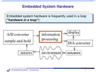
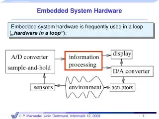
Block diagrams • which typically depict the major components of a board (processors, buses, I/O, memory) or a single component (a processor, for example) at a systems architecture or higher level. • a block diagram is a basic overview of the hardware, with implementation details abstracted out. • a block diagram can reflect the actual physical layout of a board containing these major components • The symbols used within a block diagram are simple, such as squares or rectangles for chips, and straight lines for buses. • Block diagrams are typically not detailed enough for a software designer to be able to write all of the low-level software accurately enough to control the hardware.
Schematics • Schematics are electronic circuit diagrams that provide a more detailed view of all of the devices within a circuit or within a single component • A schematic diagram is not meant to depict the physical layout of the board or component, but provides information on the flow of data in the system, defining what signals are assigned where—which signals travel on the various lines of a bus, appear on the pins of a processor, and so on. • schematic symbolsare used to depict all of the components within the system. • A schematic diagram is the most useful diagram to both hardware and software designers when trying to determine how a system actually operates, to debug hardware, or to write and debug the software managing the hardware.
conventions and rules of schematic diagrams • A title sectionlocated at the bottom of each schematic page, listing information that includes the name of the circuit, the name of the hardware engineer responsible for the design, the date, and a list of revisions made. • schematic symbols: indicating the various components of a circuit. • a label: details information about the component (i.e., size, type, power ratings, etc.). Labels for components of a symbol, such as the pin numbers of an IC, signal names associated with wires. • Abbreviations and prefixes: used for common units of measurement (i.e., k for kilo, M for mega). • Functional groupsand subgroups of components: typically separated onto different pages. • I/O and Voltage Source/Ground Terminals: positive voltage supply terminals are located at the top of the page, and negative supply/ground at the bottom. Input components are usually on the left, and output components are on the right.
Wiring diagrams • These diagrams represent the busconnections between the major and minor components on a board or within a chip. • In wiring diagrams, vertical and horizontal lines are used to represent the lines of a bus • These diagrams may represent an approximate depiction of the physical layout of a component or board.
Logic diagrams/prints • Logic diagrams/prints are used to show a wide variety of circuit information using logical symbols (AND, OR, NOT, XOR, and so on), and logical inputs and outputs (the l's and 0's). • These diagrams do not replace schematics
Timing diagrams • Timing diagrams display timing graphs of various input and output signals of a circuit, as well as the relationships between the various signals.
the rise timeor fall timeis indicated by the time it takes for the signal to move from LOW to HIGH or vice-versa. • When comparing two signals, a delay is measured at the center of the rising or falling symbols of each signal being compared. • there is a fall time delay between signals B and C and signals A and C in the first falling symbol. • When comparing the first falling symbol of signals A and B in the figure, no delay is indicated by the timing diagram.
One of the most efficient ways of learning how to learn to read and/or create a hardware diagram is via the Traister and Lisk method • Step 1. Learning the basic symbols that can make up the type of diagram, such as timing or schematic symbols. To aid in the learning of these symbols, rotate between this step and steps 2 and/or 3. • Step 2. Reading as many diagrams as possible, until reading them becomes boring (in that case rotate between this step and steps 1 and/or 3) or comfortable (so there is no longer the need to look up every other symbol while reading). • Step 3. Writing a diagram to practice simulating what has been read, again until it either becomes boring (which means rotating back through steps 1 and/or 2) or comfortable.
3.2 The Embedded Board and the von Neumann Model • all the electronics hardware resides on a board, also referred to as a printed wiring board (PW) or printed circuit board (PCB). • PCBs are often made of thin sheets of fiberglass. The electrical path of the circuit is printed in copper, which carries the electrical signals between the various components connected on the board.
the major hardware components of most boards • Central Processing Unit (CPU) - the master processor • Memory - where the system's software is stored • Input Device(s) - input slave processors and relative electrical components • Output Device(s) - output slave processors and relative electrical components • Data Pathway(s)/Bus(es) - interconnects the other components, providing a "highway" for data to travel on from one component to another, including any wires, bus bridges, and/or bus controllers
von Neumann model • The von Neumann model is a result of the published work of John von Neumann in 1945, which defined the requirements of a general-purpose electronic computer. • embedded systems are a type of computer system, this model can be applied as a means of understanding embedded systems hardware.
the major components on an embedded board • these devices are typically classified as either passive or active components. • passive components include devices such as wires, resistors, capacitors and inductors that can only receive or store power. • Active components include devices such as transistors, diodes, and integrated circuits (ICs) that are capable of delivering as well as receiving and storing power
3.3 Powering the Hardware • in alternating current (AC) and direct current (DC) circuits, the power associated with each element equals the current through the element multiplied by the voltage across the element (P = VI). • Accurate power and energy calculations must be done for all elements on an embedded board to determine the power consumption requirements. • each element can only handle a certain type of power, so AC-DC converters, DC-AC converters, direct AC-AC converters, and so on may be required. • each element has a limited amount of power that it requires to function, that it can handle, or that it dissipates. • These calculations determine what type of voltage source can be used on a board, and how powerful the voltage source needs to be.
AC is easier to generate in large amounts using generators driven by turbines turned by everything from wind to water. • AC can be transformed to lower or higher voltages much more easily than DC. • an AC-to-DC converter can be used to convert AC to the lower DC voltages required by the various components on an embedded board, which typically require 3.3, 5, or 12 volts. • Battery-powered boards don't rely on a power plant for energy, and they allow portability of embedded devices that don't need to be plugged into an outlet • Batteries have a limited life and must be either recharged or replaced
A Quick Comment on Analog vs. Digital Signals • A digital system processes only digital data, which is data represented by only 0's and l's. • On most boards, two voltages represent "0" and "1", since all data is represented as some combination of l's and 0's. • No voltage (0 volts) is referred to as ground, VSS, or low, and 3, 5, or 12 volts are commonly referred to as VCC, VDD or HIGH. • All signals within the system are one of the two voltages, or are transitioning to one of the two voltages. • Systems can define "0" as low and "1" as high, or some range of 0-1 volts as LOW, and 4—5 volts as HIGH. • signals can base the definition of a "1" or "0" on edges (low-to-high) or (high-to-low). • analog signals, which are continuous, different voltage, different frequency • a mechanism is needed on the board to convert analog signals to digital signals • An analog signal is digitized by a sampling process, and the resulting digital data
3.4 Basic Hardware Materials: Conductors, Insulators, and Semiconductors • materials that are generally classified as conductors, insulators, or semiconductors. • conductorsare materials that have fewer impediments to an electric current • Insulatorstypically have five or more valence electrons, and impede an electric current. • Semiconductors usually have four valence electrons, and are classified as materials whose base elements have a conductive nature that can be altered by introducing other elements into their structure • N-type semiconductor: Certain impurities (like arsenic砷, phosphorus磷, antimony銻, etc.), called donors, create a surplus of electrons • P-type semiconductor: acceptors, such as boron硼, produce a shortage of electrons
3.5 Common Passive Components on Boards and in Chips: Resistors, Capacitors, and Inductors • passive components commonly found on an embedded board, mainly the resistor, the capacitor, and the inductor.
3.5.1 The Resistor • carbon-composition resistors are created by the mixing of carbon (the conductor) with an insulating material (the impurity). • wire-wound resistors: creating resistors is to change the physical shape of the material to alter its resistance, such as winding a wire into a coil • types of resistors: current-limiting, carbon film, foil filament wound, fuse and metal film, • in Ohm's Law (V = IR), can be used to control current and voltage • Function: as attenuators, voltage dividers, fuses, heaters, and so on
properties • Tolerance in %, which represents how much more or less precise the resistance of the resistor. The actual value of resistance should not exceed + or - the labeled tolerance. • Power rating. indicates how much power a resistor can safely dissipate. • Reliability level ratingin %, meaning how much change in resistance might occur in the resistor for every 1000 hours of resistor use. • Temperature coefficient of resistance, or TCR: the resistor can vary with changes in temperature • positive temperature coefficient: decreases when the temperature decreases, • negative temperature coefficient: increases when the temperature decreases
types of resistors • Fixed resistors are resistors that are manufactured to have only one resistance value
Bands 1 and 2 are digits, band 3 is the multiplier, band 4 is tolerance, and band 5 is reliability.
first three bands are red = 2, green = 5, and brown = ×10. R=25x10, resistor has a resistance of 250 Ω • resistor's tolerance reflected by the red band or ± 2%, this resistor has a resistance value of 250 Ω. ± 2%. • The fifth band is a yellow band, reflecting a reliability of 0.001%. • This means that the resistance of this resistor might change by 0.001% from the labeled value (250 Ω. ± 2%) for every 1000 hours of use
Variable resistors • Resistance can be varied manually (potentiometers), by changes in light (photosensitive/photo resistor), by changes in temperature (thermally sensitive/termistor), and so on.
3.5.2 The Capacitor • Capacitors are made up of conductors typically in the form of two parallel metal plates separated by an insulator • If a wire were to connect the two plates, current would flow until both plates were no longer charged • capacitors store energy in electric fields • gives this same energy back to the circuit in its original form (electrically) when the plates are discharged • properties is considered • Temperature coefficient of capacitance • Tolerance in %
Many different types of capacitors exist (variable, ceramic, electrolytic, epoxy, and so on)
3.5.3 Inductors • Inductors store electrical energy in AC circuits. • inductors temporarily store energy in a magnetic field • Changes in current are reflected in how inductance is measured • Measured in units of henries (H), inductance is the ratio between the rate of current change and the voltage across the inductor. • V=Ldi/dt • inductors can be made up of a single wire or set of wires. Adding some type of core other than air, such as ferrite or powdered iron within the coiled-up wire increases the magnetic flux density many times over.