Download
1 / 13
130 likes | 151 Vues
This text discusses the challenges faced in implementing and operating dual harmonic RF systems at ISIS Synchrotron, including increased beam intensity, phase stable regions, and hardware failures. It also outlines future work and plans for optimization.

E N D
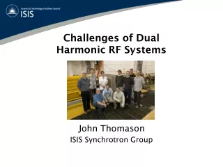
Challenges of DualHarmonic RF Systems ISIS Synchrotron Group John Thomason
Second Target Station 50 pps 40 pps
Increased Beam Intensity 1) The RFQ Accelerator • 4-rod 202.5 MHz RFQ accelerates 35 keV H−beam from ISIS ion source to 665 keV • Focuses and bunches with ~ 95% transmission efficiency (compared with ~ 60% for the old pre-injector)
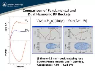
Increased Beam Intensity 2) The Dual Harmonic RF System • Fundamental RF system of six cavities (1.3 – 3.1 MHz) gives up to 140 kV/turn • Four additonal RF cavities (2.6 – 6.2 MHz) give up to 80 kV/turn
Increased Phase Stable Regions • Increased phase stable regions, enhanced bunching factors and smaller beam loss • Potentially increase accelerated intensity from 2.5x10¹³ ppp (200 µA) to 3.75x10¹³ ppp (300 µA)
2RF System Overview LPRF Controls: Amplitude, Phase & Cavity Tuning Trim Function Bunch Length Loop Anode Power Supply 2nd Harmonic Beam Compensation Loop Frequency Law Summing Amplifier Master Oscillator 1.3 MHz - 3.1 MHz Frequency Doubler 2.6 MHz – 6.2 MHz Frequency Law Generator LPF Sum Electrode Dipole Search Coil Beam Phase Loop Radial Loop Func. Gen. Variable Delay Cavity Bias Regulator Low Voltage Power Supply Existing Fundamental RF System Func. Gen. Variable Gain 1RF 2RF Driver Amplifier To Other 2nd Harmonic Cavity LPRF Systems Func Gen. Summing Amplifier Super-period Phase Splitter Phase Modulator 2 Phase Shifter RF Level Controller HPD Cavity 2nd Harmonic Cavity Voltage Loop 2nd Harmonic Cavity Tuning Loop 2nd Harmonic Cavity Phase Loop RF Detector Digital Signal Processor Gated Summing Amplifier Phase Detector (Cavity Tune) 2 RF Limiters A single Burle 4648VI tetrode is used to drive the 2RF cavity Cavity Lock LPF 2 2 Cavity Gap A Voltage Monitor Cavity Lock Servo Phase Networks RF Summing Amplifier Phase Detector (Cavity Lock) Delay Unit Cavity Bias Regulator Func. Gen 2nd Harmonic low power RF 2nd Harmonic high power RF Phase Modulation and Delay Chassis
2 × 2RF Cavity Running to TS-1
2RF Hardware Failures Anode Power Supplies • But also significant problems with intermediate amplifiers, bias regulators, cavity interlocks, LPRF modules, etc. • Problems not evident on test rig, only with beam • User cycles limited to 2 × 2RF cavities to give some spares capacity
2RF Challenges • Installation has to contend with very stringent space constraints, particularly • in the ISIS ring, but also in cable trenches and RF hall • Additional 2RF systems are notoriously difficult to get working at all on • proton machines (see experiences of IPNS team at Argonne) • System is very complex • Reliability of equipment can only be proved under limited conditions on test • rigs • Very little dedicated commissioning time with beam available • Much of this has had to be spent repairing hardware rather than actually • setting up the systems • Because ISIS can continue to run without 2RF (unlike any other of the • accelerator systems) so far whenever 2RF systems have failed during a run • operational/user pressure has dictated that it is left until the end of the run • to mend them, hence compounding the lack of running with beam and • having to use machine physics sessions to mend hardware • Target constraints on TS-1 have limited achievable intensity during some • user runs
2 × 2RF Cavity Running to TS-1 and TS-2 • 2 × 2RF cavities have been run for most of the time during • the last 10 ISIS user cycles (starting with Cycle 2006/3), admittedly • with some reliability issues and problems with mid-cycle (~ 5 ms) beam loss • TS-1 began routine running at 40 pps in Cycle 2008/3 with beam to • TS-2 being phased in during Cycles 2008/3 and 2008/4 End of Cycle 2008/4 Synchrotron average current 210 µA Beam to TS-1 Beam to TS-2
2 × 2RF Cavity Machine Physics (@ MS1/32) 3.27×10¹³ ppp injected (96%) 2.90×10¹³ ppp accelerated (93%) 2.90×10¹³ ppp extracted (100%) 20 December 2008 Average horizontal position R2BLM3 BLM sum BLM sum –(SP1+SP2) • Losses were well controlled and we ran for the majority of the 8 hour shift at this intensity • Well within BLM trip tolerances, but inhibiting on intensity • Linac pulse length was 290µs, so in theory we could operate up to this level for next user run
Future Work • Try to start Cycle 2008/5 (10 February 2009) with 180 µA to TS-1 at 40 pps • and 45 µA to TS-2 at 10 pps using 2 × 2RF cavities • Gradually improve intensity and reliability running 2 × 2RF systems during • user cycles • Optimise running with 3 × 2RF cavities and 4 × 2RF cavities during machine • physics sessions • Eventual optimised running with 4 × 2RF cavities during user cycles (when we • have a spare 2RF APS again) • Install new Master Oscillator: • new FPGA unit provides the RF • frequency sweep for 1RF & 2RF • cavities. Applies all phase • modulation (delta, anti-phasing, • geometrical offset)
Bunch 1 Bunch 2 2RF Feed-forward Beam Compensation 2RF demand Intermediate Amplifier Tetrode Amplifiers Subtracter • Now – Fixed Band Pass • Tried – 2 x “switch-in” • Later – Tuneable - Variable gain Variable delay 2RF Filter Function Generator Function Generator • Induced 2RF gap volts: • No beam compensation • Single (low frequency) • Switched (low and high • frequency)