Download
1 / 1
10 likes | 150 Vues
Heliostat. mask. window. (I,Q,U,V). Sheet polarizer. FPP. OTA: f 50cm Gregorian Telescope. FPP:. M2. HDM (Heat Dump Mirror). V. 2ndary field stop. M1. CLU (collimator Lens Unit). PMU (Polarizaiton Modulator Unit). Tip-tilt mirror. U. Q. LP. RCP. LCP.

E N D
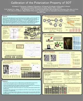
Heliostat mask window (I,Q,U,V) Sheet polarizer FPP OTA: f50cm Gregorian Telescope FPP: M2 HDM (Heat Dump Mirror) V 2ndary field stop M1 CLU (collimator Lens Unit) PMU (Polarizaiton Modulator Unit) Tip-tilt mirror U Q LP RCP LCP cR = PlRcos2qR, VR = 0.9811 sR = PlRsin2qR, PlR = 0.1496 cL = PlLcos2qL, VL = 0.9905 sL = PlLsin2qL , PlL = 0.0637 Pl = 0.9990 Calibration of the Polarization Property of SOT K.Ichimoto, Y.Suematsu, T.Shimizu, Y.Katsukawa, M.Noguchi, M.Nakagiri, M.Miyashita, S.Tsuneta (National Astronomical Observatory of Japan, Mitaka, Tokyo, JAPAN) T. D. Tarbell , R. A. Shine, C. M. Hoffmann, T.Cruz (Lockheed Martin Solar and Astrophysics Laboratory, Palo Alto, CA USA) B. W. Lites, D. F. Elmore (High Altitude Observatory, National Center for Atmospheric Research, Boulder, CO USA) and SOT Team Solar-B Science Meeting #6, 2005.11.8-11 in Kyoto 1. The polarization measurement error and SOT requirement Abstract Calibration of SOT polarization property was performed during the natural sunlight test of SOT in June 2005 using a heliostat at Mitaka. Well calibrated sheet polarizers (linear and circular) was placed on the OTA to control the incident Stokes vector, and the polarimeter response matrix, X, was determined for the spectropolarimeter (SP) and the narrowband filter instrument (NFI), where X is defined by Sout = X Sin (Sin : incidence Stokes vector, Sout : product of SOT by the onboard demodulation). The crosstalk between I,Q,U,V will be negligible after the calibration with the obtained X matrix at photometric accuracy of 10-3. The sensitivity of SOT on polarization (and also on magnetic fields) at all wavelengths observed by Narrowband Filter Instrument (NFI)are also discussed. Flow to get the Stokes vector from a polarimeter S’ = XT S = SOT product after onboard demodulation S“ = (XT)r-1 S’ = reduced Stokes vector after calibration Scale error e= 0.001 (photom.accuracy) a = 0.05 (scale tolerance) Pl = 0.15 (max. linear pol.) Pv = 0.2 (max. circular pol.) 2. Strategy of SOT polarization control SOT requirement on accuracy of XT is,, Crosstalks among I,Q,U,V should be negligible at e = 0.1% The polarization measurement error can be given by: DS = S” -S = { (XT)r-1XT- E } S ≡ D ~d(XT) S The SOT polarization has been controlled in various steps, 1) Optical elements (glass, coating, etc.) 2) Optical assemblies (CLU, CTM-TM, etc) 3) Polarimeter (FPP + CTM-TM + PMU) 4) Entire SOT sun test 5) In orbit Element and component level testings help a lot to select the best optical elements and to make entire SOT a reliable polarization instrument. - 0.3333 0.3333 0.2500 0.0010 0.0500 0.0067 0.0050 0.0010 0.0067 0.0500 0.0050 0.0010 0.0067 0.0067 0.0500 d(XT) < if (XT)r =XT + d(XT) ~ E + d(XT) assumed matrix real matrix 3. Test configuration Mueller matrix of sheet polarizers Polarization calibration of entire SOT was performed during natural sunlight using a heliostat at Mitaka. June 2005 @NAOJ cleanroom HN38 1.0000 0.9916 0.0000 0.0025 0.9989 0.9969 0.0000 0.0022 0.0145 0.0145 0.0000 -0.0003 0.0000 0.0008 0.0003 -0.0006 transmission= 0.358 Well calibrated three sheet polarizers are put on the telescope entrance at every 45 deg.. In this poster presentation, polarization calib. for entire SOT using sunlight is focused. SOT coordinate HNCP37R 1.0000 0.9866 0.0000 0.0428 0.1052 0.1047 0.0000 0.0043 -0.1064 -0.1057 0.0000 -0.0044 0.9811 0.9763 0.0001 0.0425 transmission= 0.346 4. Data reduction Example of least square fitting xij are determined by least square fitting, together with some unknowns of polarizers. HNCP37L 1.0000 0.9868 0.0000 -0.0432 0.0032 0.0034 0.0002 -0.0001 -0.0636 -0.0633 0.0001 0.0027 -0.9905 -0.9853 -0.0002 0.0430 transmission= 0.354 Symbols: observed Lines: fitting results SOT products Incident Stokes vectors determined by polarizers k = 1 ~ 12 angle 0 45 90 135 0 45 90 135 0 45 90 135deg. 5. Spectro-Polarimeter x-matrix elements vs. the scan position repeatability (See also Lites etal. ) x matrices at scan center; CCD image Measurements of two successive days are compared. dx = x(on 6/14) - x(on 6/13), scan center, median value Polarizer /angle Left 0.0000 0.0157 -0.0046 0.0064 0.0016 0.0105 -0.0041 0.0031 0.0012 -0.0047 0.0088 0.0012 -0.0024 0.0038 -0.0005 0.0073 6. Narrowband Filter Instrument (NFI) each element is scaled to median + tolerance, x00 (=1) is replaced by I-image Right 0.0000 -0.0332 -0.0027 -0.0155 0.0086 -0.0065 -0.0019 -0.0098 -0.0016 0.0049 -0.0087 -0.0019 0.0015 -0.0063 0.0016 -0.0037 Example of X matrix over the CCD, 5172, shutterless, 80x1024 Retardation of the waveplate Median Mueller matrix X matrix for NFI shutterless mode can be regarded as uniform in each left and right half of the CCD, but they have a mutual rotation of about 2.8deg. Asterisk: Left CCD Diamond: right CCD Left 1.0000 0.2205 0.0187 -0.0047 0.0012 0.4813 0.0652 -0.0014 0.0001 0.0513 -0.4803 -0.0057 -0.0025 0.0032 -0.0046 0.5256 Right 1.0000 -0.2112 -0.0170 -0.0051 -0.0025 -0.4875 -0.0560 0.0022 -0.0001 -0.0426 0.4907 0.0060 0.0027 -0.0008 0.0042 -0.5301 Each point is the median in the CCD, scale = average + 0.01, dotted horizontal lines show tolerances for each element Repeatability of measurement except the first column are within the SOT tolerance. The x matrix can be regarded as constant over the scan position The x matrix can be regarded as uniform in the CCD. Sensitivity of NFI to linear and circular polarization are determined for each wavelengths of NFI 7. Detection limit of NFI for weak magnetic fields Steps of evaluation 3) Zeeman singnal (Qz, Vz) in weak magnetic field can be given by the assumption that the Zeeman effect is a simple separation of I-profile 1) Diagonal elements of x-matrix give the polarization sensitivity of SOT Qz, Vz are Zeeman signal in spectral line Qp, Vp are SOT response left: theta= -1.571deg. 1.0000 -0.2994 -0.0336 -0.0435 0.0009 -0.4544 0.0208 0.0045 -0.0009 0.0287 0.4478 0.0068 -0.0085 0.0318 -0.0134 0.5774 right: theta= -4.441deg. 1.0000 -0.2871 -0.0305 -0.0434 -0.0003 -0.4473 0.0653 0.0038 -0.0007 0.0738 0.4435 0.0061 -0.0077 0.0310 -0.0150 0.5718 Line profile convoluted with the tunable filter profile 4) Thus detection limit for the magnetic fields are given 2) Detection limit of Qp, Vpare given by the photometric accuracy in spectral line eis photometric accuracy in continuum ~ 0.001 • Summary • ‘SOT polarization response matrix’ (X) for use in flight operation are determined with the required accuracy. • X matrix of SP can be regarded as uniform over each left and right CCD and for the scan positions. • X matrix for NFI shutterless mode can be regarded as uniform in each left and right half of the CCD, but they have a mutual rotation of about 2.8deg. which should be corrected in the data reduction. • We suggest to determine the first columns of the X matrix more accurately after launch using the continuum in data obtained in orbit. • The sensitivity of SOT on polarization at each wavelength observed by NFI was evaluated, together with its capability for detecting the weak magnetic fields. • The MgI517.2 line provides opportunities for diagnosing vector magnetic fields in lower chromosphere, NaI 589.6nm is suitable for measuring the line of sight component of B in lower chromosphere, while Ha has no sensitivity on the linear polarization. Results: Detection limit of NFI for weak magnetic fields, e = 0.001 The MgI517.2 line provides opportunities for diagnosing the vector magnetic fields in lower chromosphere, NaI 589.6nm is suitable for measuring the line of sight component of B in lower chromosphere. Ha has no sensitivity on the transversal field.