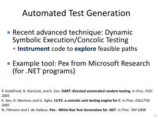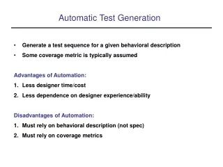
High-Level Test Generation
High-Level Test Generation. Test Generation by Enhancing Validation Test Sets*. * L. Lingappan, et al., VLSI Design, 2007 (Paper available on the class website). Basic Idea. Reuse validation test sequences Fixed control sequence, only data path values need to be determined


High-Level Test Generation
E N D
Presentation Transcript
Test Generation by Enhancing Validation Test Sets* * L. Lingappan, et al., VLSI Design, 2007 (Paper available on the class website)
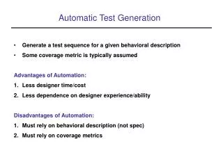
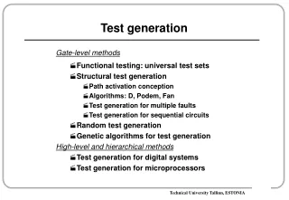
Basic Idea Reuse validation test sequences • Fixed control sequence, only data path values need to be determined • Precomputed module tests are used • If validation sequences are instruction-level, so are the generated tests • RTL level analysis means faster times SAT-Based Diagnosis
Details • Basis for analysis: • RTL circuit and controller FSM • CDFG and state transition sequence for a given validation test sequence • Not all test sequences are analyzed for all precomputed test vectors because this could be computationally expensive. Instead, heuristics are used to determine compatibility. SAT-Based Diagnosis
Process • Fault simulate validation test sequences and determine the activation time cycle for each detected fault. • If a detected fault falls within a module, the sequence is a candidate for applying precomputed test vectors • Determine compatibility of each test vector with the sequence • If compatible, then justify and propagate SAT-Based Diagnosis
Example RTL Circuit SAT-Based Diagnosis
Controller Specification SAT-Based Diagnosis
CDFG and State Transition Sequence Exercised by test T1 SAT-Based Diagnosis
Activation and Detection Cycle for Target Fault SAT-Based Diagnosis
Justification of Required Values-1 SAT-Based Diagnosis
Justification of Required Values-2 SAT-Based Diagnosis
Circuits Used in Experiments SAT-Based Diagnosis
Test Generation Results SAT-Based Diagnosis
Test Generation with Functional Fault Modleing* * Hansen and Hayes, VLSI Test Symposium, 1995, pp. 20-28.
Summary • High-level fault modeling ensuring coverage of low-level (physical or single-stuck-line) faults. • Fault effects induced from low (gate) to high (RTL or functional) level • Allows discovery of minimum test sets at the high level that are hard to find by low (gate-level) techniques SAT-Based Diagnosis
Functional Fault Models • General Faults (Universal) • Pin Faults Both of the above are implementation and technology independent • Induced faults: • Physically Induced Faults (PIFs) Derived from an implementation by the induction process, hence implementation dependent and may be technology dependent. • PIFs derived from single stuck-at faults are denoted as SIFs in the paper. SAT-Based Diagnosis
Faults, Functions, and Tests SAT-Based Diagnosis
Example • Consider the effect of some sample SAFs on the circuit function: • A SA0 • A SA1 • AP SA0 SAT-Based Diagnosis
Consider Fault Dominance: Top 6 dominate the rest, hence only need to cover these. SIFs of the Example Circuit SAT-Based Diagnosis
Minimal SIF Test Set SAT-Based Diagnosis
Dependence on Implementation (b) and (c) have fault functions not covered by those of (a). Hence require additional SIFs SAT-Based Diagnosis
Ci M Ai Bi C4 C1 C2 C0 C3 M M M M A0 A1 A2 A3 B1 B2 B0 B3 Extension to Ripple-Carry Circuit Ci+1 How many SIF tests are required for the RCC? SAT-Based Diagnosis
Test Set Sizes SAT-Based Diagnosis
Larger Examples • CLA Generator (74182) • Eliminate the logic gates for G and P in the carry circuit • Cascade the above module as in the RCC. How do the SIFs change for the module? How many tests for the whole circuit? SAT-Based Diagnosis
Tests Required for 4-bit CLA Generator SAT-Based Diagnosis
The 10 tests for CLA can be extended to cover the XOR modules. Hence 10 tests suffice for this circuit also. 4-bit Adder (74283) SAT-Based Diagnosis
CLA again dominates the test generation. 12 Tests are required, of which 10 correspond to testing CLA. ALU Circuit (74181) SAT-Based Diagnosis
Summary of Results(For Medium Circuits) SAT-Based Diagnosis
The paper goes on to apply the technique to ISCAS85 circuits. • They needed to extract high-level models for these circuits by painstaking reverse-engineering. These models are available from Prof. Hayes’ website at U. Michigan. SAT-Based Diagnosis
Conclusion • Physical fault effects induced at the functional level • Unlike prior high-level models, PIFs allow complete low-level coverage. • However, the analysis is not automatic and the results do depend on the implementation • The technique allowed obtaining provably minimum test sets for various common known implementations. SAT-Based Diagnosis