Download
1 / 8
80 likes | 263 Vues
This document presents a detailed analysis of the Gaussian beam characteristics and propagation in the focal plane based on measurements taken from the FPU CDR (July 1-3). It includes parameters such as beam waist sizes, phase angles, and Gaussianity, as well as insights from both theoretical and experimental perspectives. The findings support the development of a novel detection system with enhanced dynamic range and a fast-scan strategy for HIFI, aiming to optimize operational efficiency. A summary of future work packages is also included.

E N D
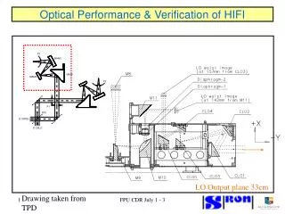
LO Output plane 33cm Drawing taken from TPD FPU CDR July 1 - 3
Best Fit fundamental Gaussian Beam E is: 0.019700, phi is: -1.196936; w_0x is: 7.547 mm; w_0y is: 7.696 mm; d_xy is: -17.945 mm; x_0 is: 0.718 mm; y_0 is: -1.198 mm; z_0 is: 127.925 mm; theta_x is: -0.092 deg; theta_y is: 0.122 deg; theta_z is: -2.852 deg; Gaussicity = 95.4%. LO Path output beam FPU CDR July 1 - 3
Channel 1 Focal plane Drawing taken from TPD FPU CDR July 1 - 3
Best Fit Fundamental Gaussian Beam E is: 0.201208; phi is: 2.999991; w_0x is: 3.898 mm; w_0y is: 3.699 mm; d_xy is: 8.082 mm; x_0 is: 0.451 mm; y_0 is: 177.060 mm; z_0 is: -39.880 mm; theta_x is: 1.117 deg; theta_y is: -0.186 deg; theta_z is: 0.706 deg;Gaussicity = 95.3%. Beam at focal plane FPU CDR July 1 - 3
Beam at secondary mirror Beam propagated to secondary mirror – Fresnel diffraction. 11dB edge taper – very close. Aperture efficiency calculations with Exp results, beam pattern on sky yet to be calculated. FPU CDR July 1 - 3
SUMMARY AND OUTLOOK (SRON) • SRON - developed an accurate and validated near-field facility • A novel differential amplitude and phase detection system has been realized. • Ultra-narrowband (down to 10 Hz) detection gives up to 70 dB dynamic range. • At each optical interface a single measurement contains all required information. • Excellent agreement – measurement/theory is now available (MSA). • MSA test strategy/analysis to be applied to rest of instrument. • Next step is to extend this technique up to higher frequencies using superconducting mixers (Channel 5). • For HIFI we plan for a fast-scan strategy which enhances the duty cycle. FPU CDR July 1 - 3
WP6 WP4 WP7 WP3 WP1 WP5 WP9 WP8 WP2 Characterisation of components Beam propagation in Telescope path Summary of Beam propagation Off line data analysis Technique analysis/selection Beam propagation in L.O. path Assessment standing waves Beam propagation in Calibration path Test execution & assistance Validation Propagation Analysis Support Work packages 2003 - 2005 FPU CDR July 1 - 3
SUMMARY AND OUTLOOK (NUIM) • Detailed work package agreed between SRON & NUIM to comprehensively model HIFI optical paths. • Complete analysis of Signal path (Common Optics Assembly) & LO Path. • Using Optical package GRASP8 (proven accuracy). • Also use Zemax, GLAD and Gaussian Beam Mode Analysis. • Work packages involves comparison of computational and experimental results. FPU CDR July 1 - 3