interference & diffraction examples
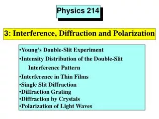
interference & diffraction examples. y. 2p. 2p. w =. k =. l. T. l. l. x. x+ l. = y(x,t). Picture made at time t = 7123670097 sec. y( x , t ) = Asin( k. t ). x – w. two variables x,t. 2p. 2p. l. l. 2 p. - t. y( x + l ,t) =. Asin( ).

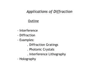
interference & diffraction examples
E N D
Presentation Transcript
y 2p 2p w = k = l T l l x x+l = y(x,t) Picture made at time t = 7123670097 sec y(x,t) = Asin(k t) x – w two variables x,t 2p 2p l l 2p - t y(x + l,t) = Asin( ) x+ l) y(x,t) y(x + l,t) (x + l) 2p 2p 2p 2p T T l T - t ) =
y(x,t) = Asin( x – t + 2*2p) y(x,t) = Asin( x – t + n*2p) = Asin( x – t) = Asin( x – t) 2p 2p 2p 2p l l l l 2p 2p 2p 2p T T T T l y(x + 2l,t) = y(x,t) y(x + nl,t) y(x + nl,t) = y(x,t) = y(x,t)
l = y(x + 5l + 0.3l,t) = y(x+0.3l,t) y(x + 5.3l,t) 1 l = = phase constant = 1080 3600 = 0.3* 0.3*
= 2 sin( )*cos( ) = 2 sin( )*cos( ) a-b kx1 + kx2 - 2wt a+b 2 2 k(x1 + x2) 2 p - wt k(Dx) k(x1 + x2) Dx 2 = 2 sin( )*cos( ) - wt l = 2 cos( )*sin( ) 2 2 k(x2 – x1) kx2 – kx1 2p Dx 2 2 2l sin(a) + sin(b) a+b a-b a b sin(kx2 - wt) + sin(kx1 - wt) Dx
if the phase difference (e2 - e1) = constant the waves are coherent x1 x1
p(Dx) k(x1 + x2) - wt = 2 cos( )*sin( ) 2 l amplitude of oscillations Dx measured in l’s min max min max min max min
cos( ) = cos( ) pDx pDx l’ l n p(Dx) pDx k(x1 + x2) n = cos( ) - wt = 2 cos( )*sin( ) 2 l l 2cos( ) p D(x n) l for different media (refractive index n) the l is shorter and l’ = l/n. xn = optical path x1n1 = optical path in media 1 x2n2 = optical path in media 2 = amplitude If (optical) path difference is nl the interference is constructive If (optical) path difference is (2n+1)l/2 the interference is destructive
d example x1 = x1+Dx x2 x2-x1=path difference Dx Dx q Dx = d sin(q) = nl for bright spots
y L Dx q q Dx = d sin(q)
example d Dx = d[sin(q) - sin(g)] = nl for bright spots Dx = d[sin(q) - sin(g)] = (2n+1)l/2 for dark spots g Dx2 Dx1 = dsin(q) g q Dx2 = dsin(g) Dx1
d1 d-d1 d path nd1+ path 1*(d-d1) n = 1.5 n = 1.5 path nd = ml for constructive path difference = nd – (nd1 + d - d1) = (2m+1)l/2 for destructive
d n = 1.16 water n = 1.33
d n = 1.16 n = 1.33 (optical) path difference is 2dn 2dn = nl constructive 2dn = (2n+1)l/2 destructive assuming incident q = 0
d n = 1.16 n = 1.33 qi d/path = cos(qr) 2 path = d/cos(qr) 2 qr path
2dtan(qr)sin(qi) 2dtan(qr) d n = 1.16 n = 1.33 (optical) path difference is 2*d*n/cos(qr) – 2dtan(qr)sin(qi) qi qi d/path = cos(qr) 2 path = d/cos(qr) 2 qr path
(optical) path difference is 2*d*n/cos(qr) – 2dtan(qr)sin(qi) 2*d*n 2dn cos(qr) cos(qr) 1 sin2(qr) 2dtan(qr)sin(qi) 2dn cos(qr) sin2(qr) 1sinqi = nsinqr Snells Law 1 = Dp nsinqr sin(qr) cos(qr) and so on = m*l constructive = (2m+1)*l/2 destructive
Michelson Interferometer mirror laser beam splitter mirror detector
Michaelson Interferometer mirror laser l beam splitter 4 mirror path difference will change by l/2 path the same detector Constructive interference will replace destructive or vice versa
Michaelson Interferometer mirror laser l beam splitter 4 mirror path difference will change by l/2 path the same detector Dp = l / 2 l/4 l/2 bright to dark next l/4 l dark to bright bright to dark next l/4 3l/2 2l dark to bright next l/4
Mach-Zehnder Interferometer detector both arms identical no path difference constructive interference (max light)
Mach-Zehnder Interferometer d d path = dn2 n2 detector n1 path = dn1 path difference Dp = d(n2 – n1) Dp intensity I = I0 |cos2(pDp/l)|
Bragg’s Law Bragg’s Law refl = incident d/sin(q)*cos(q) d path 1 = 2 path 2 = 2dcos(q) / sin(q) * cosq d sinq d sinq d sinq d sinq q q q q Dp = 2d /sinq [ 1– cos2q] Dp = 2d /sinq [ sin2q] Dp = 2d sinq = nl constructive = (2n+1)l/2 destructive
one more complication reflection = nl constructive = (2n+1)l/2 destructive one has to add l/2 to both conditions = nl + l/2 constructive = (2n+1)l/2 + l/2 destructive n1 n2>n1 = nl destructive = (2n+1)l/2 constructive n2
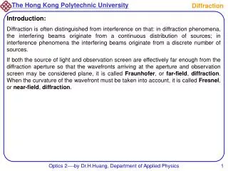
The heart of the Fabry–Pérot interferometer is a pair of partially reflective glass optical flats spaced millimeters to centimeters apart, with the reflective surfaces facing each other. The flats in an interferometer are often made in a wedge shape to prevent the rear surfaces from producing interference fringes; the rear surfaces often also have an anti-reflective coating.
A focusing lens after the pair of flats would produce an inverted image of the source if the flats were not present; all light emitted from a point on the source is focused to a single point in the system's image plane. a diffuse source set at the focal plane of a collimating lens multiply reflected to produce multiple transmitted rays
The complete interference pattern is shown. The sharpness of the rings depends on the reflectivity of the flats. The reflectivity of flats is high The reflectivity of flats is smaler (high Q factor) (low Q factor)
Rotating (Sagnac) Interferometer (from Wikipedia) A beam of light is split and the two beams are made to follow the same path but in opposite directions. The shift in interference fringes in a ring interferometer can be viewed simply as a consequence of the different distances that light travels due to the rotation of the ring.
The shift in interference fringes in a ring interferometer can be viewed simply as a consequence of the different distances that light travels due to the rotation of the ring. If a light source emits in both directions from one point on the rotating ring, light traveling in the same direction as the rotation direction needs to travel more than one circumference 2 p R - DL1 c t1 = R DL1 = Rw t1 DL1
The shift in interference fringes in a ring interferometer can be viewed simply as a consequence of the different distances that light travels due to the rotation of the ring. If a light source emits in both directions from one point on the rotating ring, light traveling in the same direction as the rotation direction needs to travel more than one circumference 4pR2 w c2 - R2w2 2pR c - Rw 2pR c + Rw 2pcDt l 2 p R - DL1 c DL1 = Rw t1 t1 = Rw t1 R 2 p R + DL2 c DL2 = Rw t2 t2 = Rw t2 DL2 Df = A w - - t2 = t1 = = t1 = c >> v