Download
1 / 27
500 likes | 1.64k Vues
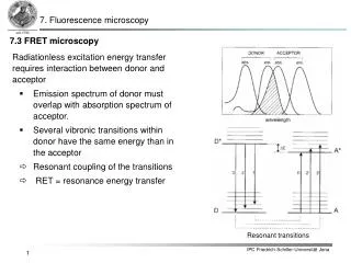
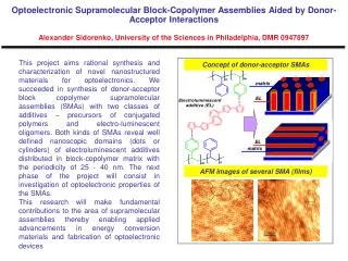
Photoinduced Electron Transfer in a Donor-Acceptor Dyad. Amy Ferreira August 14 th , 2007. Outline. Introduction Background Applications Charge Transfer Quarterthiophene-Anthraquinone (T4-AQ) Spectroscopic properties Experimental results Future goals. Background and Applications.

E N D
Photoinduced Electron Transfer in a Donor-Acceptor Dyad Amy Ferreira August 14th, 2007
Outline • Introduction • Background • Applications • Charge Transfer • Quarterthiophene-Anthraquinone (T4-AQ) • Spectroscopic properties • Experimental results • Future goals
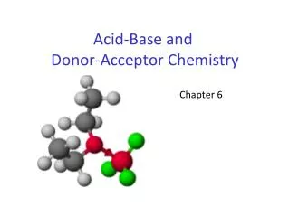
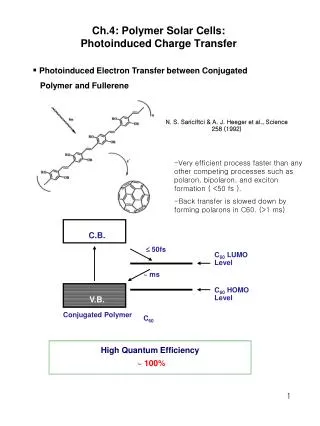
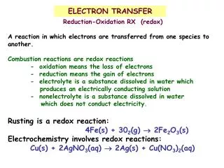
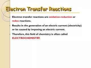
Background and Applications • Thiophenes • Have potential in photovoltaic cells, light emitting diodes, and thin film transistors • Photosynthesis • Photosynthesis occurs with no back electron transfer, while it still occurs in most man-made systems. • Charge transfer • Charge transfer through peptide bonds • Long range charge transfer
A A–. D D+. E E e– et D A D+ A– Electrontransfer Charge transfer (CT) state Ground State
Photoinduced electron transfer LUMO LUMO E E D+ et D* D A A– HOMO HOMO Locally excited (LE) state Charge transfer (CT) state
Hif A A–. D D+. Electron transfer transition state E i f DG≠ = G≠ – G0i DG0 = G0f – G0i q Marcus and Sutin Biochim. Biophys. Acta1985, 811, 265.
A A–. D D+. Electron transfer E f i DG≠ DG0 q
A A A–. D D* D+. Photoinduced electron transfer E i f DG≠ DG0 hn q
Jablonski Diagram T4*-AQ E Ket = kCS CT State Kf Knd Absorbance Kbet = kCR T4-AQ
e– Quarterthiophene-Anthraquinone Model Compound T4-COOH (Quarterthiophene-carboxylic acid) Test Compound T4-AQ (Quarterthiophene-Anthraquinone)
Lifetime ♦ T4-AQ ♦ T4a — Scatterer ♦ T4-AQ ♦ T4a — Scatterer
Femtosecond Flash Photolysis Absorbance T4-AQ in Toluene T4-COOH in Toluene
Femtosecond Flash Photolysis Absorbance T4-COOH in Acetonitrile T4-AQ in Acetonitrile
Femtosecond Flash Photolysis Lifetime T4-AQ in Acetonitrile T4-AQ in Toluene T4-COOH in Toluene
Experimental Results FC: Frank Condon factor λ: Reorganization energy W: Coulombic factor ΔG(0): Driving force ΔGs: Electrode potential correction = E00: 0-0 electron transition =
Conclusions • Solvent Polarity • Charge transfer properties have a strong dependence on the polarity of the solvent • Charge Recombination • Although the driving forces were large, the rates of charge recombination were 2-20 times slower than that of photoinduced charge separation • Inverted Marcus Region • The decrease in the electron-transfer rate constants with the increase in the driving forces for the three solvents suggests that the charge recombination processes occur in the inverted Marcus regions for the particular media
Future goals • Long range charge transfer • In proteins, efficient charge transfer cannot occur over 1.5nm, but we aim to prepare a system that mediates charge transfer over several nanometers • Currently we are preparing the redox species to affix to the sides of non-native α-L-amino acids that will mediate 3 types of charge transfer: • Tunneling, electron hopping, hole hopping
Acknowledgements • Wei Xia • Valentine Vullev • Duoduo Bao • Jiandi Wan • Radiation Lab at Notre Dame • Chak Him Chow • Vullev’s lab group
Normal vs. Inverted region E i f DG≠ > 0 DG0 q
Normal vs. Inverted region E i f DG≠ = 0 DG0 q
Normal vs. Inverted region E i DG≠ > 0 f DG0 q
Fluorometer Scheme Arc Lamp Excitation Monochromator Emission Monochromator Sample Curvet Diode Laser Scheme: an example of a spectrofluorometer for lifetime and fluorescence measurements
Chopper Sample Cell Filter Wheel CLARK -MXR CPA-2010 Pump Probe Optical Delay Rail Ocean Optics S2000 CCD Detector (7fs -1.6 ns) Ultrafast Systems Frequency Doubler 775 nm, 1 kHz 1 mJ/pulse To PC Flash Photolysis
![Blue-Colored Donor-Acceptor [2]Rotaxane](https://cdn1.slideserve.com/2419410/blue-colored-donor-acceptor-2-rotaxane-dt.jpg)