Download
1 / 36
370 likes | 538 Vues
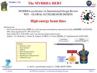
The MYRRHA HEBT. MYRRHA accelerator 1st International Design Review WP1 - GLOBAL ACCELERATOR DESIGN High-energy beam lines Starting point : the Central Design Team ( CDT ) for a fast spectrum transmutation experimental facility ( FASTEF ), EURATOM, FP7, Grant Agreement N°: FP7-232527 [1]

E N D
The MYRRHA HEBT • MYRRHA accelerator 1st International Design Review • WP1 - GLOBAL ACCELERATOR DESIGN • High-energy beam lines • Starting point : • the Central Design Team (CDT) for a fast spectrum transmutation experimental facility (FASTEF), EURATOM, FP7, Grant Agreement N°: FP7-232527 [1] • Deliverable D2.4 of the WP2, task 4. Accelerator design related issues • Authors : J.L. Biarrotte, L. Perrot, H. Saugnac (CNRS), A. Ferrari (HZDR), D. Vanderplassche (SCK-CEN) Outlook : Reference layout Beam dynamic Magnets Beam Instrumentation Mechanical design Shielding and radioprotection Additional issues L. Perrot : perrot@ipno.in2p3.fr , CNRS-IN2P3-IPNO
Introduction The R&D program for the accelerator to MYRRHA ? • The Central Design Team (CDT) for a fast spectrum transmutation experimental facility (FASTEF). It is the next step next after FP6 IP-EUROTRANS. European program : 2009-2012. • “FASTEF is proposed to be designed to an advanced level for decision to embark for its construction at the horizon of 2012 with the following objectives: to demonstrate the ADS technology and the efficient transmutation of high level waste; to operate as a flexible irradiation facility; to contribute to the demonstration of the Lead Fast Reactor technology without jeopardising the above objectives” • The Myrrha Accelerator eXperiment(MAX) : http://ipnweb.in2p3.fr/MAX/ • “To feed its sub‐critical core with an external neutron source, the MYRRHA facility requires a powerful proton accelerator (600 MeV, 4 mA) operating in continuous mode, and above all featuring a very limited number of unforeseen beam interruptions. The MAX team, made up of accelerator and reliability experts from industries, universities and research organizations, has been set up to respond to these very specific twofold specifications.” CDT = R&D reactor+HEBT MAX = R&D accelerator • Wewillbe focus on the design of the final beam line whichaims to transport the 600MeV, 4mA proton beam from the LINAC exit • up to the spallation targetlocatedinside the reactorcore, • up to the 2.4MW beam dump
1. Reference layout • HEBT : • Transfer line from accelerator to the spallation target • Prepare the beam spot requirements (shape, position, intensity and energy) • Transfer line from accelerator with the beam-dump • Provide a safe operation and maintenance • Proton Beam specifications : • ; stability to ±1% • ; stability to ±2% • Vertical injection • «donut-shape» beam footprint on the spallation window with 85mm diameter and stability to ±10% • Reliability : interruptions < 10 longer than 3sec. during a 3 months operation. The constraint is almost given by yhe accelerator
1. Reference layout From EUROTRANS [2] project, it was choosen the second conceptual design (less components and lowest high of the reactor building [3]. • General layout compatible with reactor building produced by EmpresariosAgrupados, CDT WP3 (“Plant requirements”) [4] • Beam line to reactor: layout FROZEN • Beam line to dump: not fully finish 90° bending magnet Pole-face rot.=26.565° Scanning device 24m 45° rectangular bending magnet Quad triplet • 13 quadrupoles (L=0.5m, ⌀100mm, 3T/m max) • 2 dipoles 45° (ρ=3.2m, gap 100mm, 22.5° edges) • 1 dipole 90° (idem, 26.56° edges, radiation-hard) • 16 DC steerers (L=0.3m, 150G max) • 2 AC steerers (L=0.3m, 150G max) 26.5m 30m Quad triplet Reactor • 11+ beam diagnostic boxes (11 BPMs / 8 Profilers / 1 ToF) • 12 Collimators / Halo monitors • 2 Beam Current Monitors • 1 Near-Target Profiler (PSI-like) -45° rectangular bending magnet Dump Object point 40m Matching 15m Quad triplet 38m downstream the LINAC tunnel Z=-2.5m ground 20° bending magnet +2 quadrupoles
1. Reference layout • 14 quadrupoles (L=0.5m, ⌀100mm, 3T/m max) • 2 dipoles 45° (ρ=3.2m, gap 100mm, 22.5° edges) • 1 dipole 90° (idem, 26.56° edges, radiation-hard) • 18 DC steerers (L=0.3m, 150G max), beam orbit correction • 2 AC steerers (L=0.3m, 150G max) 90° bending magnet Pole-face rot.=26.565° Scanning device 24m • Pipe aperture = 100mm, in dipole=95mm • Diagnostics boxes (in green), seelater • Beam losses have to be < 1nA/m like SNS [5] for components activation and safe maintenance • Vacuum < 10-7mbar • At the targetwindow 10-4 mbar must beachieve (beam losses ~0.05nA/m) • In case of incident with the beam in the HEBT : Tswitch-off<50ms. 45° rectangular bending magnet Quad triplet 26.5m 30m Quad triplet Reactor -45° rectangular bending magnet Dump Object point 40m Matching 15m Quad triplet 38m downstream the LINAC tunnel Z=-2.5m ground 20° bending magnet +2 quadrupoles Diagnostics
2. Beam dynamic studies • By construction, the line: • is achromatic at 1st order (position & divergence on target independent of beam energy) : T16=T26=0 from LINAC to target • has telescopic properties at 1st order (image size on target = 9 x object size at point 0) : T11=T33=9 between object point and target. Target beam size is control by the beam size at the matching object point 0. • Donut-shape beam footprint achieved with the AC scanning magnets. Circular movement with few tens of Hz • No focusing during the last 25m (reactor hall) QP10-12 QP7-9 O QP1-3 QP4-6
2. Beam dynamic studies 600MeV Protons beam envelopes at 3RMS, using TraceWin Code [6] Normalized emittances: ex=0.242, ey=0.234, ez=0.291 p.mm.mard T46 vertical dispersion Horizontal plane in blue, vertical plane in red Without scanning O Beam phase space on the spallation window Without scanning : RMSX,Y=9mm Beam phase space at the LINAC exit
2. Beam dynamic studies • Target aspects: Why do you need the beam scanning ? • Beam scanning must be done in order to protect the Pb-Bi target window • But : • No space is involved inside the reactor hall (no quad, no instrumentation) • Safety do not permit to install the scanning device after the last 90° dipole • Donut shape is impose by the Pb-Bi liquid target cooling • Maximum beam scanning amplitude is fixed by target windows + last 2 meters beam pipe penetration inside the reactor core • Scanning speed depend almost to target windows and Pb-Bi speed cooling • Need to 2 scanning dipoles located before the last 90° vertical dipole the maximum amplitude have to be less than 150G with frequency close to 100Hz (not yet frozen) • The scanning devices not yet design Scanning 25m -- Horizontal-- Vertical Reactor Beam phase space on target with scanning 13kW/2.4MW Target window zone
2. Beam dynamic studies • Impact of a energy jitter • The beam target foot-print have to be not sensitive to primary beam energy variation, which is ensure by the first order achromatic line • But between dipole, beam shift centroide is dependant to T16. Therefore, dedicated instrumentation have to be install like collimators, ring losses or segmented collimators. X Plane Effect of a 0.5% beam shift energy (3MeV / 600MeV) Collimators / rings • “donut-shape” footprint • Use to a raster magnets on X and Y, using a (possibly redundant) set of fast steering magnets operated at frequencies of several tens of Hz • Central trajectory is continuously deviate. The ±9 mm RMS beam spot on target is moved around the window centre in a circular pattern of radius 20 mm. • Octupole expander solution is not feasible (see next slide) Y Plane Collimators / rings Target window zone Beam spot movement
2. Beam dynamic studies Multipole beam expander ? • Homogeneous beam density distribution can also be performed using a set of octupole magnets in front of the target: • The first set of octupoles (1 or 2) produces a square homogeneous footprint • An additional turned octupole transforms the square in circle 120mm 60mm • This is a beautiful solution, but several drawbacks: • Produces a lot of beam halo => has to be located near the final target 1. Impossible in our case 2. Tested location: upstream. Unmanageable (unless a possible 2nd order O-I system ...?) • Extremely sensitive to any beam misalignment or beam size variation => For MYRRHA, it seems extremely complicated (if not impossible) to implement
2. Beam dynamic studies QP10-12 QP7-9 O QP1-3 QP4-6 • Tuning method : • Set the magnets to their theoretical value, & send a very low duty cycle beam (10-4) • Adjust DC steerers for orbit correction (alignment) • Adjust QP1-3 => tune beam waist on 0 w/ desired size (1mm rms), using 3 transverse beam profil detectors • Adjust QP7-13 => achromaticity optimization using beam position monitor, target optical diagnostic. • Adjust QP 4-6 => re-adjust desired beam size on target (9mm rms), check telescopic properties • Recheck alignment & switch on + tune scanning device for obtain the “donut-shape” on target • Increase step by step the beam duty cycle (chopper in the LEBT)
2. Beam dynamic studies Statistical error study • Static errors are randomly applied to: • Magnets (displacement, field error) • Input beam (position, divergence, energy, emittance, intensity, mismatch) • The beam tuning procedure is simulated step by step: • - static errors are corrected when possible • - errors on beam diagnostics measurements are taken into account • Dynamic errors (mechanical vibrations, stability... ) are then randomly applied: • - These transient errors are not corrected • - Applied to magnets (displacement, field error) & input beam (position, divergence, energy, emittance, intensity, mismatch) • Iteration is performedto get good statistics: • 100 different line configurations • each one with a tracking involving 105 macro-particles
2. Beam dynamic studies Error calculations 1. Nominal 99% envelopes without errors, without scanning
2. Beam dynamic studies Error calculations 2. 99% envelopes with UNCORRECTED static errors (random distribution) , without scanning
2. Beam dynamic studies Error calculations 3. 99% envelopes with CORRECTED static errors (same random distribution) , without scanning
2. Beam dynamic studies Error calculations 4. 99% envelopes with CORRECTED static errors + uncorrected dynamic errors, without scanning
2. Beam dynamic studies Error calculations: beam losses • Possible losses on collimator: • Min = 0, Max = 29kW • Mean = 0.3 kW, RMS = 3kW • => Losses in 1% cases • Losses on final tube: • Min = 0.5kW, Max = 110kW • Mean = 15 kW, RMS = 14kW from 107 particles
2. Beam dynamic studies Error calculations: trajectories Meanorbit (X) Mean orbit (Y) RMS orbit (X) RMS orbit (Y) • This error study is quite insufficient to get to definitive conclusions, but gives already good orders of magnitude for the required tolerances and a good feeling of the general situation. We need a end-to-end accelerator errors calculation
2. Beam dynamic studies Error calculations: target footprint : fluctuations are considered acceptable Y rms size X rms size Footprint (linear scale) Footprint (log scale)
2. Beam dynamic studies Error calculations: sensitivity • Errors impacting the orbit excursionthrough the line (i.e. beam losses) • Beam energy jitter: ±1MeV => 5 mm rms deviation (DYNAMIC) • BPM precision: ±0.5mm => 2 mm rms deviation (STATIC) • Magnets alignement: ±0.3mm => 1 mm rms deviation (STATIC) • Dipole field stability: ±2.10-5 => 0.5mm rms deviation (DYNAMIC) • Errors impacting the position on target • 1. Input beam divergence jitter: ±0.01mrad => 0.7mm rms (DYNAMIC) • 2. Input beam position jitter: ±0.1mm => 0.6mm rms (DYNAMIC) • 3. Dipole field stability: ±2.10-5 => 0.5mm rms (DYNAMIC) • 4. Quadrupoles mechanical vibrations: ±10mm => 0.4mm rms (DYNAMIC) • 5. Beam energy jitter: ±1MeV => 0.3mm rms deviation (DYNAMIC) • 6. Dipole mechanical vibration (Y): ±10mm => 0.2mm rms (DYNAMIC) • Errors impacting the spot size on target • 1. Quadrupoles gradient stability: ±10-3 => 0.15mm rms (DYNAMIC) • 2. Beam energy jitter: ±1MeV => 0.1mm rms (DYNAMIC) • 3. Beam profiler precision measurement: ±0.5mm => 0.1mm rms (STATIC)
2. Beam dynamic studies Beam line to dump Tuning the beam line from p-source up to HEBT (commissioning, tuning & check) • Present layout of the line: • 20° dipole to avoid neutron back streaming & ease the maintenance • 2 quadrupoles to defocus beam on dump with 210mm diameter • 240mm larger beam vacuum pipe along the final 6m • Beam dump design • Preliminary design from the 1 MW PSI proton dump (larger) • Required shielding, preliminary study performed • Detailed mechanical & thermal assessments to be done • Power losses = 2-3kW/cm² • 600MeV protons range in Copper = 25cm 3s beam envelops 15m
3. Magnets Quadrupoles • 2 series of quadrupoles : 14 for the beam main HEBT line (Q-50), 2 for the beam-dump line (Q-100) • Quadrupole design & size choose for minimize fringe fields & others higher orders contribution • Current density from 2 up to 10 A/mm² • Water cooling < 10 bars • Radiation-hard materials (low carbon steel) Design can be closed to the SNS quadrupoles
3. Magnets Dipoles • 600MeV protons => Br=4 Tm => Dipole radius = 3.2m • 4 magnets • 3 angles of deviation : 20° (beam-dump line), 45° (x2) and 90° (up to reactor) • C-type magnets (except for 20° magnet) • Reliability have to be taking into account (coils design) • Radiation-hard materials especially for 90° and 20° magnet POISSON calculation of a basic 90° dipole magnet for MYRRHA/FASTEF. 2. 10-4 Field homogeneity is achievable in the “good field region”. Design can be closed to the CNAO cancer therapy facility in Italy [7]
3. Magnets Steering and scanning magnets • Steering magnets are used for the orbit correction • DC power supply • Number = 18 (9 for horizontal plane, 9 for vertical plane) • Magnetic length = 30cm • Aperture = 110mm • Working range : -500G<B<500G • RMS operating value = 85G • Scanning magnet : produce the beam «donut-shape» on the Pb-Bi window • AC power supply • Number = 2 (X&Y) or 4 for redundancy • Magnetic length = 30cm • Aperture = 110mm • Working range = -150G<B<150G • Frequency : to be defined (~few hundreds of Hertz) Orbit correction DC steerer used at the CNAO facility (Italy) Prototype of a 500 Hz 500G scanner magnet developed at Los Alamos for the APT project [8]
4. Beam Instrumentation Overview Beam diagnostics and control systems will be deployed all along the final beam transport line in order to tune the beam, maintain normal operation according to specifications, and protect the beam line equipments in case of malfunctioning. • beam intensity measurement current monitors (accuracy <1%), • beam loss monitors for trigger interlocks for beam switch off (DT<1ms) • Optical system (VIMOS like system at PSI [9] for beam footprint on target monitor and survey. For MYRRHA, need a dedicated R&D • Couple of halo scrappers and wire profilers should also be used if possible (this will probably not be the case) in the last straight section for redundancy. • At the exit of the 90° bending magnet, halo monitors for checking the beam center and size are roughly correct. • Standard beam diagnostics (position and size) Diagnostics type and usage for beam transfer line Main beam diagnostic devices along the HEBT
4. Beam Instrumentation Few details Beam profiler : electron secondary emission or wire scanner Energy : ToF technique = 3 pick-up capacitive electrodes PSI BPM: capacitive pick-ups or magnetic loops symmetrically arranged in the pipe wall SPIRAL2 SPIRAL2 L=20 needed to obtain (𝜕𝐸/𝐸)<10-3 PSI • Target monitoring : measure the beam size + position close the target. Crucial & challenging measurement for MYRRHA • Beam have to be monitored continuously (deviation from tight reference values and peak power density feed-back). • Optical technic like VIMOS (at SINQ - PSI) or TIS (SNS): • Thermal incandescence • Cr/Al2O3 fluorescence • Optical transition radiation (OTR) • He fluorescence (fromfill gaz in line) Halo & Losses : tuning phase + safety (machine protection) : <1nA/m loss level Current : fundamental for the reactor monitoring Loss Ring : particle interactions induce currents, size adapted to the beam size, material Cu, Ni, Mo or C, cooling may be necessary, sub-sections can be useful BLM: detectors implantation around the beam tube. 6 along the HEBT to ensure the 1nA/m loss level DCCT : average beam current ACCT : single bunch monitoring TM01-mode coaxial resonator (aluminum, with a 10μm coating layer of silver to improve the electrical conductivity) SPIRAL2 PSIionisation chamber PSI SPIRAL2
5. Mechanical design • First conceptual design of the whole high energy part of the line and its integration inside the reactor building. • We take into account the design of the reactor and the definition of the building • Separated in different parts, due to the various security constraints • Safety requirements have an important impact on the building design, the accessibility and the mounting/dismounting procedures
5. Mechanical design • Part 1 : • beam axis =+1.5m to the floor • Corridor 5m large • Beam line not centered (3m right) for accessibility • No crane • alignment done with “Laser Tracker” • Part 2 : • 45° inclined line, length = 30m • Part of the beam dump casemate in this hall • Crane of 50 tons capacity • BD line in a 20° deviation. Reduction of the neutrons backscattering and better access for the handling • Part 3 : • Tunnel of 22 metres long, 6.5 metres large and 10 metresheight • Crane of 50 tons capability, common with part 2 • 10-7 mbar vacuum specification (not yet study) : • Vacuum components and fittings will be ConFlat® type • Turbo-molecular pumping group with 200 l/s capacity. • 1 pump placed each 3m. • Each component subjected to alignment adjustments (magnets, diagnostic boxes, collimators…) has to be installed using bellows allowing enough longitudinal and lateral displacement.
5. Mechanical design • Part 4 : 90° magnet zone • Backscattered neutrons from reactor => hot cell probably • Need to specific material, remote handling and nuclear waste capabilities • Pumping system of the vertical line & 90° dipole will be in this section (200l/s turbo + 16m3/h primary) • 50 tons crane • Fast valve before and after concrete wall • Vertical port for beam foot-print detection system and/or neutron dump coming from reactor. • Part 5 : Beam line inside the reactor hall • High activation zone. • Need complete isolation, full remote and lateral handling. • Less active components must be chosen • Reactor access imposed to dismount the line • No pumping system in this section • 3 parts for the line • Alignment is a major concern • Vacuum at the spallation window fixed to 10-4mbar • 2 Fast valves (15ms closing time) for protection against the window breaking and accelerator failure (like cryogenic accidents)
10 m 30 m 9 m • 5. Mechanical design Part 6 : Beam line casemate: Conceptual design • A 2.4 MW, full power beam dump, based on the 1.2 MW PSI proton beam dump, is foreseen to allow the commissioning of the MYRRHA accelerator independently from the reactor. • The conceptual design of the MYRRHA beam-dump is taken from the 1.2MW PSI existing dump [10]. • Dump is handled from the top using the common 50 tons crane (part 2 & 3). • Due to the 20° deviation. It is not necessary to dismount the line. • Beam power deposition on 6 blocks (PSI=4 blocks), length=3m • Material : Copper but need to be optimized considering the high level of activation. High density carbon fiber surrounded by stainless steel can by a useful alternative The beam dump casemate=Hot cell 15 m deep, concrete wall to 5m thickness, 20 tons crane Structure of the 1.2 MW PSI proton beam dump
6. Shielding and radioprotection • The goal of the shielding design is to guarantee that, under normal operational conditions, the added integrated dose to anybody working around the FASTEF/MYRRHA accelerator is extremely small, i.e. comparable or smaller than the natural background. To reach this goal one must rely on: • the use of conservative beam loss assumptions; • the use of a conservative shielding model; • the assumption of an occupancy factor = 1, that means 2000 hours/year occupancy close to the outer shielding wall (at the maximum dose rates). • First evaluations have been performed during the PDS-XADS project, considering a continuous 1 nA/m proton loss at 600 MeV. This is equivalent to a mean beam loss level of about 0.6 W/m. Required concrete/earth combined thickness at 600 MeV to reach the 0.5 μSv/h dose rate level. For 600MeV protons • Shielding issues in the reactor building impact strongly on the 90° dipole shielding. Concrete walls and roofs up to 5 m thick would therefore be needed to reach the 0.5 μSv/h dose rate outside the facility. • Shielding issues around the beam dump : the BD design must satisfy the shielding requirements & minimize the backscattered neutron & minimize the BD activation
6. Shielding and radioprotection Activation • Main problems : • Activation of the elements devoted to the beam absorption (beam dump) • Activation of the material of the line due to beam losses • Calculations preformed using the FLUKA MonteCarlo code [11] which give : • Particle fluences • Ambient dose equivalent • Time evolution of the activation products (build-up and decay of radionuclides) Calculation on various “targets” (Carbon, Copper, AlSl-316L, Aluminium, Iron) Neutron fluence (n/cm2 per beam proton) in and around the target Residual (in μSv/h) around 100 m beam-line, for two representative cooling times after a short and a long-term irradiation. Residual dose rate around the carbon target, at different cooling times
6. Shielding and radioprotection Optimisation of the beam dump zone Full absorption of the 600MeV protons beam We have already presented a structure closed to the 1.2MW PSI beam-dump. Advantage of the know how but secondary neutrons and activation are very high. We have explore an alternative solution for the safety studies with a soft material as dump core (Carbon) surrounded by a high-Z shielding structure (stainless steel). Smaller neutron yield and less activation problems. Dose rate (in mSv/h) Neutron fluence (n/cm2 per primary proton) in the dump concrete cage of the dump casemate Copper core Copper core Carbon core + stainless steel Carbon core + stainless steel The soft Carbon core solution is clearly a good candidate Beam dynamic and mechanical integration not yet study
7. Additional issues Adaptation of the final layout The building detailed definition is still in progress, and will probably keep moving slightly until the start of the MYRRHA construction. It is therefore important to ensure that the beam line layout will be able to adapt to these changes as much as possible without major consequences. Possible beam line adaptations in the case of a reactor height increase Study of a radiatively cooled cold window Vacuum protection of the final beam line in case of a target window failure Third passive protection in addition to the fast valves : use a thin metallic foil able to sustain high temperature gradients without perturbing too much the beam optics. In existing (low-power) accelerators, titanium foils of a few hundreds of μm are typically used. Study of a 100mm diameter 400mm thick Titanium using LISE++ code [12]. Eloss=0.33MeV, Ploss=1.3kW => fusion of the window (need to have a 30cm beam size (including halo) which is not reasonable. Using a cold window seems to be quite unrealistic Study of a water cooled cold window • SNS/JPARC : Inconel 718 (1.5 to 2 mm thickness) separated by a 1.6 to 3 mm gap in which water flows (at typically 10 bars) • ESS project : Aluminum tube cooled by Helium at 40 bars • Apply to our case with the SNS/JPARC solution, Ploss=27kW • Beam emittance increase by a factor 10 (sx’,y’ from 0.4mrad up to 4mrad) => not compatible with a window location at 25m up to the spallation window • Activation of this cold window • Need to be located very near the target itself • SNS feedback can be an extremely important issue for MYRRHA J-PARC ESS prototype
Conclusion HEBT for the MYRRHA project A beam line from the LINAC up to the reactor • The goal of the MYRRHA/FASTEF final high‐energy beam line is to safely inject the proton beam onto the spallation target located inside the reactor • Consolidated design of the beam line to reactor achieved • AC steering magnets are preferred for the beam scanning • Error study shows very robust behavior (sensitivity in the X-plane may be optimised) • Need start-to-end error studies • Near-target optical device appears to be mandatory to be able to correctly tune and monitor the beam shape on target. • First detailed mechanical design is described for each part of the line • First shielding and activation calculations have been performed • Beam dump design on-going, need to be study in details (structure…)
References J.L. Biarrotte, L. Perrot, H. Saugnac (CNRS), A. Ferrari (HZDR), D Vanderplassche (SCK-CEN), Accelerator design related issues, February 2012, deliverable D2.4 of the WP2 task 4 to the CDT project, Seventh Framework Program EURATOM, Grant Agreement N° FP7-232527 J-L. Biarrotte et al. – “Accelerator design, performances, costs & associated road-map”, Deliverable (D1.74) of the EUROTRANS project, March 2010. L. Mansini – Minutes of the CDT WP2 3rd technical meeting, Mol, 14-15 November 2010. Drawings package N° 092-204 by Empresarios Agrupados. J. Galambos – “Operational experience with high power beams at the SNS superconducting linac”, Proc. of the LINAC’2008 conference, Victoria, Canada. TraceWin Code : http://irfu.cea.fr/Sacm/logiciels/index.php W. Beeckman et al, “Magnetic design improvement and construction of the large 90° bending magnet of the vertical beam delivery line of CNAO”, Proc. Of the EPAC 2008 conference, Genoa, Italy. M.E. Schuze et al., “Testing of a Raster Magnet System for Expanding the APT Proton Beam”, Proc. of the PAC’99 conference, New York, USA. K. Thomsen, “VIMOS beam monitoring for SINQ”, Proc. of the DIPAC’2009 workshop, Basel, Switzerland. See http://aea.web.psi.ch/Urs_Rohrer/MyWeb/pkanal.htm A. Ferrari, P. Sala, A. Fassò, J.Ranft, “FLUKA: A multi-particle transport code”, CERN-2005-10 (2005), INFN/TC_05/11, SLAC-R-773. O.B. Tarasov, D. Bazin, “LISE++: Radioactive beam production with in-flight separators”, NIM B 266 (2008) 4657–4664.