Download
1 / 1
20 likes | 141 Vues
38 cm. 183cm. Amplifier schematic. 1 st 2 nd stage. 2 detector stations, symmetric in z. X. Non-irradiated/irradiated Agilent FE comparison. TAS events: t = 12.5, 37.5 .. ns. Interactions: t=0, 25, 50 .. ns. Δ.

E N D
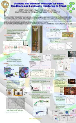
38 cm 183cm Amplifier schematic 1st 2nd stage 2 detector stations, symmetric in z X Non-irradiated/irradiated Agilent FE comparison TAS events: t = 12.5, 37.5 .. ns Interactions: t=0, 25, 50 .. ns Δ Si diode signal Si diode noise Gali-52 amplification ν [MHz] ν [MHz] ν [MHz] 44 m BCM modules ATLAS BCM Pixel 2.8 days @ B =2 T BCM @ 45° Diamond Pad Detector Telescope for Beam Conditions and Luminosity Monitoring in ATLAS M. Mikuž1,V. Cindro1, I. Dolenc1, H. Kagan5, G. Kramberger1, H. Frais-Kölbl4, A. Gorišek2, E. Griesmayer4, I. Mandić1, M. Niegl4, H. Pernegger2, W. Trischuk3, P. Weilhammer2, M. Zavrtanik1 1Univ. Ljubljana/Jožef Stefan Institute, Ljubljana, Slovenia, 2CERN, Geneva, Switzerland, 3University of Toronto, Toronto, Canada, 4FHWN, Wiener Neustadt, Austria, 5Ohio State University, Columbus, USA Abstract Beam conditions and the potential detector damage resulting from an anomalous event such as a full LHC bunch blasting into the collimators have provoked LHC experiments to plan their own monitoring devices in addition to those provided by the machine. ATLAS decided to build a telescope with two stations of four diamond pad detectors each. Equipped with fast electronics with shaping time of 1 ns it allows time-of-flight separation of events of beam anomalies from normally occurring p-p interactions. Placed symmetrically about the interaction point at z=±183.8 cm and r~55 mm (η~4.2) it will provide also a coarse measurement of the ATLAS LHC luminosity. The stringent timing requirement to resolve signals half a bunch crossing apart, coupled with the radiation field of ~1015 π/cm2, prompted the usage of 500 μm thick pCVD diamond pad detectors of 1x1 cm2, operated at an unconventionally high electric field of 2 V/μm. Two diamonds are glued back to back and tilted at 45° to the tracks to enhance the signal. Two stage high-bandwidth low-noise pre-amplifier composed of discrete components provides signal amplification of ~ 40 dB, with signal rise time of 1 ns, pulse width of 3 ns and base-line restoration in 10 ns. Low-loss coaxial cables are used to lead the signals ~14 m outwards, where they are processed in the NINO time-over-threshold timing amplifier-discriminator ASIC, thus preserving timing and amplitude information. Further processing of the optically transmitted signals, including timing coincidence and amplitude analysis, and event history tracing that could eventually lead to a beam abort request, is foreseen by an FPGA-based system in the ATLAS service cavern. Ten detector modules have been assembled and subjected to tests, from characterization of bare diamonds to source and beam tests. The latter were performed last December at KEK and this summer in the CERN PS and SPS beams. A silicon telescope for efficiency evaluation across the detectors has been used for the CERN beam tests. Final electronics and services were used. Based on performance, eight of the modules will be selected for installation on the pixel support structure by the end of this year. • Goals • Provide distinctive signature of beam anomalies in ATLAS such as • Beam scraping at TAS collimators: single 7 TeV proton yields ~ 1 MIP/cm2 around beam-pipe, serious detector damage from complete beam loss • Beam gas interactions • Stand alone device providing information about genuine interactions • Monitoring of interactions at LHC start-up • Luminosity assessment: on-line and off-line • Front-end electronics • Two stage Fotec HFK500 amplifier • 1st stage: 500 MHz Agilent MGA-62563 GaAs MMIC low noise amplifier (A = 22 dB, NF = 0.9 dB) • 2nd stage: Mini Circuits Gali-52 InGaP HBT broad-band micro-wave amplifier (A = 20 dB) • Amplifiers tested for radiation hardness • Up to 1015/cm2 reactor neutrons and protons from CERN PS • Agilent: ~ 20 % amplification loss observed with Si diodes, no noise increase • Gali-52: 0.5 dB amplification loss • FE amplifier OK for BCM application Amplifier in module box • Working principle • Distinguish interactions from background via time of flight • With two symmetric stations at ±Δz/2 • Interactions: in time • Background: out of time on one side by Δt = Δz/c • At high luminosity expect ~ one hit per side for each bunch crossing • Interactions at Δt = 0, 25, 50 … ns • Optimal separation of background at Δt = 12.5 ns ⇒ Δz = 3.8 m • Requirements • Fast signals • Rise-time ~ 1 ns • Width ~ 3ns • Base line restoration in ~ 10 ns to prevent pile-up • Single MIP sensitivity • S/N ~ 8 for perpendicular MIP before irradiation • Installation close to the beam pipe at η ~ 4.2 • Radiation hardness up to 30 MRad ( 1015π/cm2 ) • No possibility for maintenance – robust detector • BCM module tests • Bench tests • 30 MBq 90Sr source; ~ MIP signal • QA for BCM modules • Module stability tests • Noise independent of HV • Good reproducibility of signals • Signal stable to 4 % during 24 h • Beam test at KEK in December 2005 • Few GeV/c pion beam • BCM signal amplified in 300 Mhz Ortec • Recorded by CAEN 2 GHZ sampling ADC • Tracking by MWPC (T3, T4) • Parasitic to Belle PID upgrade test • BCM signal required in trigger 90Sr waveform Signal: max 34-36 ns Noise: all data 0-20 ns • Realization • Two stations with four detector modules each • Mounted on pixel support structure at z = ±183.8 cm • Sensor at r ~ 55 mm, about 20 mm from the beam pipe • Bandwidth optimization • FFT analysis of average BCM MIP signal • Confirmed in CERN SPS test beam, 200 MHz BWL on LeCroy LC564A: signal decrase by 1.5, noise by 2 → S/N increase by 4/3 • KEK beam-test results • S/N ~13; caveat: noise estimate • BCM in trigger • Asymmetric amplifier • Coarse MWPC tracking • Extrapolation to BCM • Scattering in material • Qualitativeperformance estimates only • Beam test in CERN PS and SPS in summer 2006 • CERN PS: T11 & T9 line (3.5, 12 GeV) • CERN SPS: H6 & H8 line ( >100 GeV) • 4 BCM modules read out • Analogue readout: ORTEC + CAEN ADC • TOT readout: NINO + CAEN ADC • Final HV/LV supplies (ISEG, SCT) • Final HV/LV cables & connectors • Final signal coaxes (GORE 1.4 m & Heliax 12 m) • Bonn Si telescope for precision tracking (4H, 4V planes) • Special thanks to Bonn telescope crew (Jaap, Lars, Markus) • BCM inside telescope: good tracking, cuts on scattering • Sensors • Polycrystalline CVD diamond sensors chosen • Radiation hard – shown to work at > 1015 particles/cm2 • Fast signals – high velocity and cut-off due to trapping • Small leakage current – no cooling required • Procurement in collaboration with CERN RD-42 • Sensors produced and conditioned by Element Six Ltd. • Metallized with proprietary radiation hard process at OSU • Sensor properties • Size 10 mm x10 mm, active 8 mm x 8 mm (metallization) • Thickness ~500 μm • Charge collection distance ~220 μm • Holds ~ 2 V/ μm, operating voltage 1000 V, current ~ nA • Sensor assembly – two sensors back-to-back at 45° to increase signal • Signal ⊗ 1.4, noise unchanged for 0 → 45° • Signal ⊗ 2, noise ⊗ ~1.3 for single → double-decker • Mounted on Al2O3 ceramics, through-holes and bonds supply HV to top/bottom, signal sourced from middle • Erratic leakage currents in pCVD diamonds • Leakage current increases by factor >100 on day’s time-scale • Erratic behaviour on time-scale of minutes • Phenomenon observed at BaBar at lower fields 1 V/μm • Excess current vanishes in magnetic field > 1 T • BCM noise insensitive of current in nA ↔ μA range BCM signal cable (black) BCM HV/LV cable (red) Sensor with Au test metallization BCM adapter box (~PP2) Set-up in SPS H8 test beam Sensor on ceramics in module box BCM modules in holder H8 pion beam Bonn Si telescope • NINO back-end chip tests • Differential timing amplifier-discriminator (1 ns peak, 25 ps jitter) • LVDS output with width proportional to time-over-threshold • Radiation tolerant design by CERN-MIC • Signal split 1:12 into two inputs to increase dynamic range • Tests confirm suitability asBCMback-end chip • Analysis of CERN PS TOT data • Quasi on-line analysis • Si tracks with hits in all planes • Central diamond region • Efficiency vs. NINO threshold • Noise occupancy vs. threshold • Efficiency saturates at > 95 % • Preliminary analysis of CERN PS analogue data • 3 runs from 12 GeV T9 beam • 22 k events with good Si tracks (hits in ≥ [3V,3H] planes) • Central diamond region chosen • Signal: max in 2 ns window • Noise: single sample well before signal, fit positive values • S/N ~ 14 ± 2, consistent with KEK and source tests Typical BCM pulse NiNO TOT response to 1-4 MIP signals BCM signal 22 k events with good Si telescope tracks X-Y @ 1st Si Cut @ 180 1.7 k events with Si tracks inside red box Signal MPV~280 Noise 20±2.6 Mail to: Marko.Mikuz@ijs.si X-Y for signal > 180