Download
1 / 21
290 likes | 551 Vues
2D- Photonic Crystals based on Vertical Cavity Surface Emitting Lasers (VCSELs) arrays. Presentation for the Photonic Crystal Course, June 2009. Elodie Lamothe Ing. Microtechn . Dipl. EPF PhD . Student in Photonic School LPN EPF Lausanne. Plan of the Presentation. Introduction

E N D
2D-Photonic Crystals based on Vertical Cavity Surface Emitting Lasers (VCSELs) arrays • Presentation for the Photonic Crystal Course, June 2009 ElodieLamothe Ing. Microtechn. Dipl. EPF PhD. Student in Photonic School LPN EPF Lausanne
Plan of the Presentation • Introduction • Vertical Cavity Surface Emitting Laser (VCSEL) • Photonic crystal based on VCSEL • Modellisation of VCSELs-array • Formalism of coupled mode theory • Fabry-Perot cavity model • Equivalent 3D photonic crystal model • Optical Properties • Homogeneous structures • Heterostructure and mode confinement • Coupling between two confine modes • Conclusion Plan of the Presentation
Introduction Plan of the Presentation Introduction
VCSEL Description p-contact hole p-DBR (AlGaAs/GaAs) active region(InGaAs) n-DBR(AlGaAs/GaAs) electron n-contact • Two Distributited Bragg Reflectors (DBR) define the cavity • Light is amplified by stimulated emission in the active region • Emission of the ligth through the lower DBR (n-DBR) Plan of the Presentation Introduction
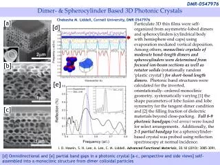
Photonic Crystals based on VCSEL • Photonic crystals are obtained by modulatingthe reflectivity of the top DBR reflector: => RAu>RCr • p-contact • 2D-Photonic crystal • Active Photonic crystal • Au • Cr • Such structures incoporate gain and losses • Optical Bloch waves are stimulated at each lattice site • Optical coupling • n-contact • Optical coupling between adjacent microcavities via diffraction of the optical field at the edges of the pixels • Au • Cr • H. Pier and al., Nature (London), 407,880-883, 2000 Plan of the Presentation Introduction
Condition on the wavelength • Usual photonic crystals • Photonic crystal based on VCSELs • Condition • Bragg condition • Photoniccrystalbased on VCSEL have lattice constants significantlyexceeding the opticalwavelength. • Only the transversal component of the wavevectorundergoes Bragg condition • |kp| << |kz| Plan of the Presentation Introduction
Modellisation Introduction Modellisation
Couple Mode Theory (CMT) • 1) Consider an isolated waveguide (WG) • propagation constant • 2) Electric field distribution is obtained by solving Helmolz equation for each WG • => Set of orthogonal eigenmodes • 3) Each solitary WG is placed in a periodic lattice • => slight perturbation of the fields at the WG • => weak coupling between adjacent WGs • Total field : • SUPERMODE = superposition of the separated orthogonal WG modes Introduction Modellisation
CMT applied to 3x3 homogeneousarray • Near fields Amplitude • Far fields Intensities • Out-of-phase mode • Limited far field • pattern • In-phase mode Introduction Modellisation
Fabry-Perot cavity approach • Replace the bottom DBR and the top DBR by mirrors with modulated reflection • 2) Consider the VCSELs-array as a Fabry-Perot cavity with an effective length Leff • Cavity description by Rayleight-Sommerfeld diffraction integral • Rayleight-Sommerfeld integral is solved iteratively by numerical computation. • A. E. Siegman, Lasers, University Science, Mil Valley, CA, 1986 Introduction Modellisation
Equivalent 3D-Photonic Crystal (1) … • 1) VCSEL cavity is unfolded => an effective 2L-periodicity along z-axis is induced. • 2) The reflections at the DBR are replaced by thin equivalent layers • 3) The resulting 3D-PhC is analyzed using Orthogonal Plane Wave expansion method • G. Guerrero, PhD Thesis, Thèse N°2837, EPFL, Lausanne, Switzerland, 2003 • D. L. Boiko and al., Opt. Express,12, 2597-2602, 2004 Introduction Modellisation
Equivalent 3D-Photonic Crystal (2) Brillouin zone of the equivalent 3D photonic crystal • Model of the VCSEL-based photonic crystal • T • • Z • Master Equation • 2D-Hamiltonien eigenvalue problem in transversal plan • paraxial approximation • small reflectivity modulation • G. Guerrero, PhD Thesis, Thèse N°2837, EPFL, Lausanne, Switzerland, 2003 • D. L. Boiko and al., Opt. Express,12, 2597-2602, 2004 Introduction Modellisation
Band Diagram • Parameters • Photon energy • Mode Losses Imaginary part of the eigenvalue Real part of the eigenvalue => No Bandgap for photon energy => Bandgap in terms of losses Lowest loss mode T5 • Bloch theorem Phase difference between complex reflection coeffecient Au and Cr out-of-phase relationshipbetween adjacent lattice site • L.D.A. Lundeberg and al., IEEE J. Top. Quant. Elec., 13,5, 2007 Introduction Modellisation
Lowest Loss Mode:Simulations of the Optical Field • Near Field • Geometrical Model • Numerical Solution of Master Equation • Amplitude • Phase • Far Field • pi phase shift between adjacent VCSELs • Frauhenofer • diffraction • out-of-phase coupling between VCSELs • L.D.A. Lundeberg, Thèse N°3911, EPFL, Lausanne, Switzerland Introduction Modellisation
Optical Properties Modellisation Optical Properties
Homogeneous Structures • Near Field Patterns • Far Field Patterns • Stimulated • Emission • Stimulated • Emission • Spontaneous • Emission • 4 lobes • out-of-phase • lasing mode • H. Pier and al., Nature (London), 407,880-883, 2000 Modellisation Optical Properties
Modes Confinement • Confinement Structure • Mode confinement can be achieved by creating photonic crystal heterostructure • Domain with lower fill factor FF presents higher loss • Rectangular shape PhC island with higher FF in a sea of lower FF material confines supermodes • Numerical Calculation • Measurement • out-of-phase relationship between adjacent VCSEL elements is maintain • L.D.A. Lundeberg and al., App. Phys. Lett.,87, 241120, 2005 • L.D.A. Lundeberg and al., IEEE J. Top. Quant. Elec., 13,5, 2007 Modellisation Optical Properties
CoupledIslands • Structure • Numerical Analysis • Near Field • Far Field • FFisland = 0.694 • FFsea= 0.25 • λ=960nm • Λ=6μm |B> |A> • Far field intensity distribution of one principal lobe along θx • Coupling between two islands • Bonding state |B> • Anti-bonding state |A> • L.D.A. Lundeberg and al., App. Phys. Lett.,87, 241120, 2005 Modellisation Optical Properties
CoupledIslands • Measurement • Modal loss considerations • Bloch part of the wave function gives an out-of-phase relationship between adjacent pixels: Bright fringe in the centre of the lobes => Bonding state |B> is lasing • |B> : This phase relationship is maintained => lowest loss • |A>: This phase relationship is altered => higher loss • L.D.A. Lundeberg and al., App. Phys. Lett.,87, 241120, 2005 Modellisation Optical Properties
Conclusion • 2D-Photonic Crystal can be realized using VCSEL-array • The lasing supermode predicted by simulation and experiments presents an out-of-phase relationship between each pixel • Well designed heterostructures can confine the supermode • A coupling between two confined supermodes can be achieved • => This coupling results in a bonding state. Optical Properties Conclusion
Questions Thankyou for your attention Questions Conclusion