Slab Form Design
290 likes | 830 Vues
Slab Form Design. Lecture 5. Slab formwork. Parts of typical slab formwork. Slab formwork. Design Steps: Step 1: Estimate design loads Step 2: Sheathing thickness and and spacing of its supports (joist spacing) Step 3: Joist size and spacing of supports (stringer spacing)

Slab Form Design
E N D
Presentation Transcript
Slab Form Design Lecture 5
Slab formwork Parts of typical slab formwork
Slab formwork • Design Steps: • Step 1: Estimate design loads • Step 2: Sheathing thickness and and spacing of its supports (joist spacing) • Step 3: Joist size and spacing of supports (stringer spacing) • Step 4: Stringer size and span (shore spacing) • Step 5: Shore design to support stringers • Step 6: Check bearing stresses • Step 7: Design lateral bracing
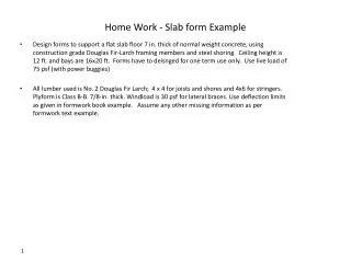
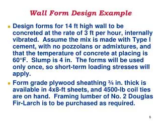
Slab form Example • Design forms to support a flat slab floor 8 in. thick of normal weight concrete, using construction grade Douglas Fir-Larch forming members and steel shoring. Ceiling height is 8 ft. and bays are 15x15 ft. Since forms will have continuing reuse, do not adjust base design values for short term load.
Slab form Design Example • STEP 1: ESTIMATE LOADS: • Dead load, concrete and rebar, [8 in. / (12 in./ft.)]x 150 pcf = 100 psf • Minimum construction live load on forms 50 psf (refer to lecture #1) • Weight of forms, estimated 8 psf Total form design load 100 + 50 + 8 = 158 psf
Slab form Design Example • STEP 2: SHEATHING DESIGN: • Assuming 3/4-in. form grade plywood sheathing, from Tables 4-2 and 4-3: • Fb = 1545 psi • FS = 57 psi • E = 1,500,000 psi • S = 0.412 in.3 • I = 0.197 in.4 • Ib/Q = 6.762 in.2
Slab form Design Example • STEP 2: SHEATHING DESIGN: • Tables 4-2 and 4-3, for plywood:
Slab form Design Example • CHECK BENDING • For design purposes, consider a 1-foot-wide strip of plywood. Then: • Substituting in the equation:
Slab form Design Example • CHECK DEFLECTION • For D = l/360: • For D = 1/16”:
Slab form Design Example • CHECK ROLLING SHEAR • For design purposes, consider a 1-foot-wide strip of plywood. Then: • since Vmax = 0.6wL ,so: or: • Substituting in above equation:
Slab form Design Example • From the above calculations, l = 20.8 in. governs. • Meaning that joist supports CANNOT be more than 20.8 inches apart. • HOWEVER, in order to select the span, we must consider the size of the plywood sheets and equal spacing of supports. • In this case, 5 equal spaces of 19.2 inches on an 8-ft. wide plywood sheet will be appropriate.
Slab form Design Example • STEP 3: JOIST SIZE AND SPACING OF STRINGERS TO SUPPORT THE JOISTS: • Check 2x4 construction grade Douglas-Fir-Larch as joist (forms are used repeatedly, so there is no short-term load adjustment). • From Table 4-2: Fb = 1000 psi and FV = 95 psi and should be adjusted for horizontal shear by a factor of 2. E = 1,500,000 psi.
Slab form Design Example • From Table 4-1B, for S4S 2x4s: bd = 5.25 in.2, I = 5.36 in.4, and S = 3.06 in.3
Slab Form Design Example • CHECK BENDING • CHECK DEFLECTION • For D = l/360
Slab Form Design Example • CHECK SHEAR • Using the horizontal shear stress formula for a uniformly loaded continuous beam (similar to calculations on page 19): • Or L = 4.69’x12 in./ft. = 59.5 inches
Slab Form Design Example • Comparing the three spans calculated above, l = 38.1 inches governs. • Considering 15x15 ft. bays and desire for uniform spacing, 36 inch spacing is a reasonable number. • This means that the spacing of stringers will be at 5 equal spaces per bay.
Slab form Design Example • STEP 4: STRINGER SIZE AND SPAN: • Use 4x4 Construction grade Douglas-Fir-Larch stringers. From Table 4-1B for S4S 4x4s: bd = 12.25 in.2, I = 12.50 in.4, S = 7.15 in.3; and d = 3.5 in. • CHECK BENDING
Slab Form Design Example • CHECK DEFLECTION • For D = l/360 • CHECK SHEAR • Use the horizontal shear stress formula for a uniformly loaded continuous beam:
Slab Form Design Example • From the above calculations, l = 42.5 in. governs. • Meaning that stringers CANNOT be more than 42.5 inches apart (span of stringers). • HOWEVER, in order to select an appropriate span, we must consider the dimensions of the bay. • The 15-ft. bay could be divided into 5 equal spaces of 36 inches (180”/5 = 36”) which is less than the maximum allowable span of 42.5 inches.
Slab Form Design Example • Alternatively, we can check the possibility of using a deeper stringer, i.e. 3x6, in order to increase the shore spacing. • Since bending is dominant here, we will check bending for a 3x6 member. • For S4S 3x6s from Table 4-2: Fb = 1000 psf, and from Table 4-1B, S = 12.60 in.3 • Now we can use 45-in. support spacing for the 3x6 stringers, which will divide the bay into 5 equal spaces.
Slab form Design Example • STEP 5: SHORE DESIGN: • Stringers are placed 36-inches apart, supported by shores spaced 45 inches apart. The area of support for each shore is: • Then the total load per shore is:
Slab form Design Example • Schematic design:
Slab form Design Example • Refer to Table 7-11 for wood shoring material. Both 3x4 and 4x4 are more than adequate to carry 1778 lbs for an effective length of 8 ft.
Slab form Design Example • Step 6: Check Bearing Stresses: • Bearing should be checked where stringers bear on shores and where joists bear on stringers. • Stringers bearing on shore: • Assume the head piece of the adjustable steel shore is 11½x3 5/8". The 3x6 stringer is actually 2½ in. thick.
Slab form Design Example • If the headpiece is placed parallel to the stringer, bearing area is 2½x11½ 0r 28.75 in.2. Bearing stress will be: • This is well below the base Fc, which is obtained from Table 4-2 (the value of compression to grain, Fc, for No. 2 24 Douglas Fir-Larch is 625 psi).
Slab form Design Example • Joist bearing on Stringers: • The two members are 1½ and 2½ in. wide. • Contact bearing area = 2½x1½ = 3.75 in.2 • Average load transmitted by joist to stringer is: Joist spacing x joist span x form load Bearing at this point is also low relative to the 625 psi base value for Fc.