Culvert Top Slab Design Using Opis
Culvert Top Slab Design Using Opis. VOBUG Conference August 3 rd , 2010 Nashville, Tennessee Robert LeFevre, P.E. Adam Price, P.E. Tennessee Department of Transportation Structures Division. Background.


Culvert Top Slab Design Using Opis
E N D
Presentation Transcript
Culvert Top Slab Design Using Opis VOBUG Conference August 3rd, 2010 Nashville, Tennessee Robert LeFevre, P.E. Adam Price, P.E. Tennessee Department of Transportation Structures Division
Background • Before 2000, Tennessee’s cast-in-place reinforced concrete box and slab culverts were designed and built as frames. • Very thick top and bottom slabs under deep fill • Solution: • Change culverts from frames (moment connections) to only shear connections at wall to slab interfaces. • For fills greater than 10 feet, top bars in top slab and bottom bars in bottom slab are broken at interior walls to ensure simple span action. • Shear at interior supports is less for simple spans than for continuous spans • Greatly reduced top and bottom slab thicknesses
Assignment • The current culvert designs are according to the AASHTO Standard Specifications. • In order to receive federal funding, FHWA requires all culverts to be designed according to the AASHTO LRFD Specifications after October 2010.
Solution • Since Tennessee uses pinned connections to connect the culvert top and bottom slabs to the culvert walls, the top slab may be modeled in Opis as a slab bridge. • Excel spreadsheets were written to design the exterior walls, interior walls, and bottom slabs.
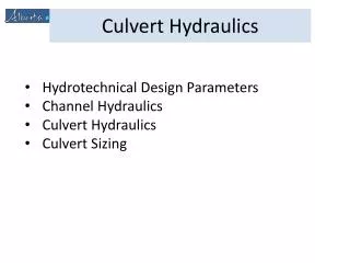
Culvert Sizes • Culvert sizes covered by standard drawings (clear width x clear height): • Smallest: 1 cell 6ft. X 3ft. • Largest: 3 cells 18ft. X 18ft.
Live Load Distribution Factors (LLDFs) For a 14’ cell width, no fill, single cell,LLDF = 0.1240.
AASHTO LRFD 4.6.2.10Equivalent Strip Widths for Box Culverts “This Article shall be applied to box culverts with depth of fill less than 2.0 feet.” “Design for depths of fill of 2.0 feet or greater are covered in Article 3.6.1.2.6.”
AASHTO LRFD 4.6.2.10Equivalent Strip Widths for Box Culverts TDOT’s culvert design is based on Case 1: Traffic Travels Parallel to Span. The axle load is distributed perpendicularly to the span over a width ‘E’.
Calculating ‘E’ E = 96 + 1.44S E = 96 + 1.44 x 14’ E = 116.16” E = 9.68’
AASHTO LRFD 4.6.2.10Equivalent Strip Widths for Box Culverts “When traffic travels primarily parallel to the span, culverts shall be analyzed for a single loaded lane with the single lane multiple presence factor.” From AASHTO LRFD 3.6.1.1.2, the single lane MPF = 1.2
Calculating the LLDF LLDF = (1/E) x MPF LLDF = (1/9.68’) x 1.2 LLDF = 0.1240 lanes
AASHTO LRFD 3.6.1.2.6Distribution of Wheel Loads Through Earth Fills “…where the depth of fill is 2.0 feet or greater, wheel loads may be considered to be uniformly distributed over a rectangular area with sides equal to the dimensions of the tire contact area… and increased by…the depth of the fill...”
AASHTO LRFD 3.6.1.2.5Tire Contact Area “The tire contact area...shall be assumed to be a single rectangle whose width is 20.0 inches and whose length is 10.0 inches.”
AASHTO LRFD 3.6.1.2.6Distribution of Wheel Loads Through Earth Fills
Live Load Distribution Width ‘E’ Cell width = 14’ Single cell 3’ fill case E = (20” + 2’) x 2 E = 88” E = 7.333’
Calculating the LLDF LLDF = (1/E) x MPF LLDF = (1/7.333’) x 1.2 LLDF = 0.1636 lanes
AASHTO LRFD 3.6.1.2.6 Distribution of Wheel Loads Through Earth Fill “Where the live load and impact moment in concrete slabs, based on the distribution of the wheel load through earth fills, exceeds the live load and impact moment calculated according to Article 4.6.2.10, the latter moment shall be used.”
Calculating the LLDF no fill case LLDF = 0.1240 lanes 0.1240 < 0.1636 Therefore, LLDF = 0.1240
Live Load Distribution Width ‘E’ Cell width = 14’ Single cell 5’ fill case E = (20” + 3’) x 2 E = 112” E = 9.333’
Calculating the LLDF LLDF = (1/E) x MPF LLDF = (1/9.333’) x 1.2 LLDF = 0.1286 lanes
Calculating the LLDF no fill case LLDF = 0.1240 lanes 0.1240 < 0.1286 Therefore, LLDF = 0.1240
Live Load Distribution Width ‘E’ Cell width = 14’ Single cell 10’ fill case E = 6’ + 20” + 5’ E = 152” E = 12.667’
Calculating the LLDF LLDF = (1/E) x MPF LLDF = (1/12.67’) x 1.2 LLDF = 0.0947 lanes
Calculating the LLDF no fill case LLDF = 0.1240 lanes 0.1240 > 0.0947 Therefore, LLDF = 0.0947
Live Load Distribution Width ‘E’ Cell width = 14’ Single cell 20’ fill case E = 6’ + 20” + 10’ E = 212” E = 17.67’
Calculating the LLDF LLDF = (1/E) x MPF LLDF = (1/17.67’) x 1.2 LLDF = 0.0679 lanes
Calculating the LLDF no fill case LLDF = 0.1240 lanes 0.1240 > 0.0679 Therefore, LLDF = 0.0679
Live Load Distribution Width ‘E’ Cell width = 14’ Single cell 30’ fill case Neglect live load.
AASHTO LRFD 3.6.1.2.6 Distribution of Wheel Loads Through Earth Fill “For single-span culverts, the effects of live load may be neglected where the depth of fill is more than 8.0 feet and exceeds the span length…”
AASHTO LRFD 3.6.1.2.6Distribution of Wheel Loads Through Earth Fills minimum fill depth = 20’ span length = cell width = 14’ {fill = 20’} > {8’} {fill = 20’} > {span length = 14’} Therefore, LL may be neglected.
AASHTO LRFD 3.6.1.2.6 Distribution of Wheel Loads Through Earth Fill “For multiple span culverts, the effects of live load may be neglected where the depth of fill exceeds the distance between faces of end walls.”
Live Load Distribution Length ‘L’ cell width = 14’ single-cell 5-foot fill case L = 10” + 3’ L = 46” L = 3.833’
Live Load Distribution Length ‘L’ cell width = 14’ single-cell 10-foot fill case L = 10” + 5’ L = 46” L = 5.833’
AASHTO LRFD 3.6.1.2.6 Distribution of Wheel Loads Through Earth Fill Where…areas from several wheels overlap, the total load shall be uniformly distributed over the area.
Live Load Distribution Length ‘L’ cell width = 14’ single-cell 20-foot fill case L = 10” + 10’ L = 130” L = 10.833’
Dynamic Load Allowance, IM IM = 33% for Limit States other than the Fatigue and Fracture Limit State.
3.6.2 Dynamic Load Allowance: IM3.6.2.2 Buried Components The dynamic load allowance for culverts and other buried structures…shall be taken as: IM = 33 x (1.0 – 0.125 x DE) >= 0
For the three-foot fill case: IM = 33 x (1.0 – 0.125 x DE) IM = 33 x (1.0 – 0.125 x 0’) IM = 33%
For the five-foot fill case: IM = 33 x (1.0 – 0.125 x DE) IM = 33 x (1.0 – 0.125 x 3’) IM = 20.6%