Culvert Material Selection Guide
This guide provides steps for material selection in culvert design, covering field reviews, culvert hydraulics, structural strength, service life, and material analysis. It includes plan alternates and design examples for effective decision-making.

Culvert Material Selection Guide
E N D
Presentation Transcript
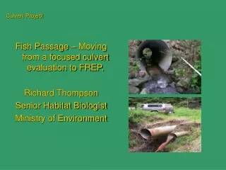
Culvert Design Material Selection Central Office Hydraulics
Steps for Material Selection • Field Review • Culvert Hydraulics • Structural Strength • Service Life • Material Analysis • Plan Alternates
Field Review • Determine pH of the water • Use an instrument that is capable of accuracy of 0.1 • Use Figures 1002-2 through 1002-3 only if no flow is present when performing the field check
Do not use unless there is no flow when performing the site visit.
Field Review • Determine if there is a presence of abrasive material. • Abrasive Material – Presence of gravel, stones, or a course sand in the barrel of an existing conduit (or in the existing stream bed) that has a stream gradient or flow sufficient to cause movement of the abrasive material. • Assume abrasive conditions if there is any question about the bed material.
Field Review • Investigate the condition of existing structures. • If a replacement structure, look at the existing structure. • If a new structure look at any adjacent existing structures.
Culvert Hydraulics • Use approved methods outlined in the Location and Design, Volume 2 Manual
Structural Strength • Structural strength for Metal Conduits (steel and aluminum) • Select the gauge thickness and corrugation profile that is adequate (based upon fill height). • Figures 1008-1 through 1008-9 (steel) • Figures 1008-15 through 1008-21 (aluminum) (NOT Aluminized)
Structural Strength • Structural Strength for Concrete Conduits • Select the D-load that is adequate for structural strength (based upon fill height). • Figures 1008-10 through 1008-14
Service Life • Service life is either 50 or 75 years • Use 50 years as a minimum . • Use 75 years for high fills (>16’), under freeways, or where future costs may be high to replace the structure.
Service Life • Durability for Metal Conduits • Use the obtained pH and abrasiveness observation to determine the gauge thickness. • Use figures 1002-5(50) through 1002-6(75) & the general notes for the figures.
Service Life • Durability for Concrete Conduits • Check for adequate service life based upon the pH, pipe slope, and pipe rise. • Use figure 1002-4.
Material Analysis • For metal conduit, choose the higher gauge thickness from the structural design, or the durability analysis. • When durability thickness is higher than structural thickness, provide the 1-inch corrugation profile for pipe diameters over 48 inches.
Plan Alternates • Place all available material options in the plan (all metal alternatives and concrete). • In some cases, only one material may be specified in the plan: • If the outlet velocity in a concrete pipe requires a ring chamber and the velocity of the metal alternative is below 20fps, then metal may be used exclusively. • When encountering excessive cover for a concrete pipe.
Plan Alternates • Where a larger corrugated metal pipe would require a higher pavement grade to satisfy minimum cover requirements, concrete may be used exclusively. • Where a metal pipe arch is required hydraulically and a round concrete pipe would work, concrete may be used exclusively. • Do not need to specify minimum D-loads or minimum gauge thicknesses in the item call-out.
Plan Alternates • Show the following in the plan: • D-load or gauge thickness if it is above the minimum shown in the specifications. • The conduit shown in the plans should be the longest length pipe (the smallest diameter). • Hydraulic Design Information • Other information (see L&D, Vol. 3, Section 1312.2)
Example Problem Given: • Hydraulic design requires 96 inch corrugated or 90 inch smooth lined • Outlet velocities: • Corrugated: V=17.0 fps & Smooth lined: V=21.0 fps • Height of cover = 18 feet • Under a new alignment (minor state route) • pH was measured and found to be 7.5
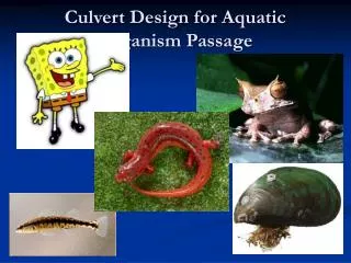
Design Example Photo from creek: Is this Abrasive?
Example Problem Select the appropriate design alternatives. • As per L&D, we will exclude concrete conduit in the design due to the velocity of 21 fps. • Durability Design • Site was determined to be abrasive in nature • A design service life of 75 years will be used due to the high fill height. • Use Figure 1002-6(75) for the durability design
Example Problem • Options from figure & notes are: • 10 gauge 707.02 Aluminum Coated • 12 gauge 707.07 Aluminized & Asphalt Coated & Paved • 14 gauge 707.04 Polymer Coated with 1” corrugations • 16 gauge 707.04 Polymer Coated & Asphalt Coated & Paved • 16 gauge 707.02 with Concrete Field Paving • 1 gauge 707.03 • 12 gauge 707.03 with Concrete Field Paving • 707.22 (aluminum pipe) with Concrete Field Paving • 707.23 (aluminum structural plate) with Concrete Field Paving
Example Problem • Structural Design of Metal Conduit • Use Figure 1008-1 & 1008-3 to check for maximum height of cover:
Example Problem • A gauge thickness of 0.064 (16 gauge) will be satisfactory up to a fill height of 31 feet for all steel options except for 707.03 (structural plate). • A gauge thickness of 0.109 (12 gauge) will be satisfactory up to a fill height of 29 feet for steel structural plate. • A thickness of 0.105 (the minimum for this size) will be satisfactory up to a fill height of 20 feet for aluminum pipe. • A thickness of 0.100 (the minimum for this size) will be satisfactory up to a fill height of 20 feet for aluminum structural plate.
Example Problem • Specifying in the Plan • Specify the alternative as per L&D, Volume 3, Section 1312.3. • For this example it would be as follows: • 603 – 180 L.F. 96” Conduit, Type A 707.02 (0.138) Aluminized, 707.02 with CFP, 707.03 (0.280), 707.03 with CFP, 707.04 (1”) (0.079) Polymer Coated, 707.04 (1”) Polymer Coated Asphalt Coated and Paved, 707.07 (0.109) Aluminized Asphalt Coated and Paved, 707.22 with CFP, 707.23 with CFP