Download
1 / 20
340 likes | 1.22k Vues
Prepared by: Eng. Haider Mohammed Jasim. SEMINAR IN ADVANCED STRUCTURE analysis and design of box culvert.

E N D
Preparedby: Eng. Haider Mohammed Jasim SEMINAR IN ADVANCED STRUCTURE analysis and design of box culvert
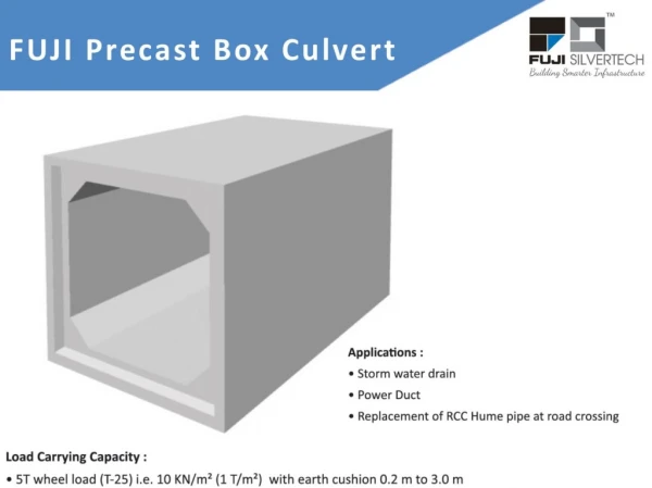
- Box culvert is hydraulic structure consisting of two horizontal and two vertical slabs built monolithically are ideally suited for a road or railway bridge crossing with high embankments crossing a stream with limited flow reinforced concrete rigid frame box culverts with square or rectangular openings are used. Four-sided culverts are typically referredto as box culvertsmade of single or multiple cells for passage of fluid, usually storm water for small discharge single ceiled box culvert is used and for larger discharges multi ceiled box culvert can be employed. - Precast reinforced concrete (RC) box culverts are very common and usually constructed as single or multicell culverts. INTRODUCTION
When the box culvert loading to test purpose , the first crack occurred at mid-span of the top panel at approximately 124.5 kN.This cracking load was comparable with the theoretical cracking load of 112.5 kN, computedbased on elastic behavior. The following cracking occurred at the negative moment region at thetop of the wall panels. Two cracks occurred simultaneously on both walls at approximately142.3 kN. Final cracks occurred at the negative moment region of the top slab panel atapproximately 155.7 kN, the maximum load attained during the test. the figures below show locationand sequence of cracking. Occurrence of each crack was accompanied by an increase in mid spandeflection caused by stiffness degradation.
APPLICATIONS • Short-span bridges (over highways, waterways, railways, for golf courses, etc.) • Conveyance of storm water, sewage or industrial wastes (storm drains) • Provide for emergency egress, as with this tunnel
GENERAL INFORMATION - box culverts are economical due to their rigidity and monolithic action and separate foundations are not required since the bottom slab resting directly on the soil serves as raft slab. -Three side culvert Placed on strip footing and used for short span bridges but the size of this type grater than the four side box culvert Designs are dependent on project specifications and applications and the shape of this type is (U) shape and some time takes (arc) shape. Pre cast box culvert more suitable from cast -in -place - . culvert installing is easy and more controlBox-
Design and Analysis • Design Criteria • - AASHTO Standard Specifications for Highway Bridges and wastewater applications • AREMA Manual for Railway Engineering • ACI 318, for tunnels and special design and ACI 350R, for wastewater applications • Analysis Methods • - Finite Element Analysis • - Moment Distribution • - AREMA Chapter 8, Part 16 formulas • - Beam Formulas • - Reinforced Concrete Analysis • Design Procedure • 1-Determine the applied loads using the appropriate design criteria. • 2- Investigate load cases which will give the maximum positive and negative bending moments in the walls. • 3-Determine the maximum shear and bending moments using the selected analysis method. • 4-Calculate the required wall thickness and reinforcing steel area to satisfy the appropriate design criteria.
FINDING DIMENSION OF BOX CULVERT From manning formula:- Q=Awhen R= the hydraulic radius . S= the slope of channel . And friction losses and losses of inlet and out let:. +k (inlet) + k(out let) • Obtaining : ( (General equation to calculate the dimensions of box culvert • -In this formula the cross section is taken • square immediately and get the initial • dimension and then can find correct • needed according to requirements of the project • - Initial value of thickness of box culvert • assume by dividing the clear width • over twelve • thickness= • and then correct this thickness • according to deflection or shear effect
ANALYSIS AND DESIGN OF BOX CULVERT -The design span length and wall height should be based on the centerline-of-member to centerline-of-member dimensions -The structural design of a reinforced concrete box culvert comprises the detailed analysis of the rigid frame for moments , shear forces and thrusts due to various types of loading condition -The box culvert is analyzed for moments , shear force and axial force due to various loading condition by any of classical methods such as moment distribution , slope deflection and column analogy procedures - The used method in design is the working stress method to avoid any crack because the any small crack can cause to erosion in steel bar and then failure. outlined below:.
1- The weight of embankment and deck slab and the track load are considered to be uniformly distributed load on the top slab. • weight of fill+ • weight of live load and • Impact load + weight of top concrete slab. Weight of top slab= density of concrete ×thickness of box culvert. weight of fill =density of fill × the height from edge of street to the edge of top slab (N). • weight of live and Impact load
2-The self weight of two side wall acting as concentrated loads are assumed to produce uniform soil reaction on the bottom slab. total concentrated load ) ) The weight of two wall
3-The earth pressure on the vertical side walls of the box culvert is computed according to the columns theory. W1= (weight of fill+ weight of live and impact load ) × factor of lateral earth pressure . W2=W1+ weight of column soil (density ×length of wall )
4- When the culvert is full with water the pressure distribution on side walls is assumed to be triangular with a maximum pressure intensity in the base ,Water Pressure Culverts should be designed assuming static water pressure on the inside of the walls. Water pressure =density of water ×height of water
5-The soil reaction on the bottom slab is .assumed to be uniform Reaction of soil= weight of top slab +weight of two walls
THE LOADS APPLIEED CRITERIA The load applied depend on :. • The depth and the slope of fill and the types of soil such as (saturated or partial saturated ) and the condition of soil (passive or active or rest condition ) • The type of live load applied according to the type of street (highway, sub Street ,etc…) and also Surcharge loads from nearby impact loads • The level of water inside the box culvert( full water box culvert , partial, and empty ) and the type of flow in side of box culvert (laminar or turbulent flow ) • Seepage under foundation if occur the uplift pressure applied on the floor of box culvert but commonly the value of this pressure is very small . • Seismic loads where applicable.
DESIGN BOX CULVERT IN EMPTY CASE AT DEPTH (4.1m) :- After we calculate the applied load from the case of load we draw the load diagram . From manning formula the dimension (3×5.33×0.4 m)
COMPUTE MOMENT DIAGRAM ACCORDING TO MOMENT DISTRIBUTION METHOD . -The effect of shear stress and axial stress can be negligible
To design consider one way slab and find reinforcement Ø10@ 13 cm c/c Ø28@ 12.5 cm c/c -Minimum reinforcement in long direction for temperature Ø10@ 13 cm c/c Ø10@ 13 cm c/c Ø32@ 11.5 cm c/c Ø32@ 11.5 cm c/c Ø10@ 13 cm c/c Ø32@ 11.5 cm c/c
SPECIAL CASE WHEN STREET SLOPING:- -DIFFERENT DISTRIBUTION LOAD IN THIS CASE AND THE RESULT MOMENT LARGER VALUE FROM NATURAL CASE .