PIPE CULVERT
PIPE CULVERT. By CH. VENKATARAMAIAH.

PIPE CULVERT
E N D
Presentation Transcript
PIPE CULVERT By CH. VENKATARAMAIAH
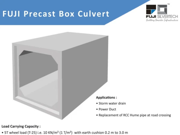
(1) A pipe culvert is normally proposed where a canal with a discharge of 1 cumec to 1.5 cumec crosses the village/ Z. P / R & B roads. In case the number of rows of pipes exceeds ‘2’ the pipe culvert may not be economical. In such cases the slab culvert may be economical. The culvert shall be with full formation width of road as per IRC recommendation.
(2) Pipe (i) Maximum & Minimum diametre of pipe: The maximum diameter of pipe should be 1200 mm and minimum diameter should be 750 mm. It shall be designed to function as partially flowing with the velocity not more than 2 times the normal canal velocity. (ii) Class of pipe: NP3 class (reinforced concrete, medium – duty, non pressure pipe), conforming to I.S 458 – 2003 / 1988. (iii) Minimum Earth cushion: Minimum earth cushion over the pipes shall be 600 mm.
(3) Bedding: Irrespective of load coming on the pipe, they shall be bedded in a cradle constructed of concrete having mix not leaner then M 15 grade. Thickness of concrete below the pipe should be ¼ th of internal diameter of pipe and on the sides the concrete should extend to ¼ th of external dia. Figure A Figure A
Where bed rock or boulders strata is met with at the pipe invert level, the excavation shall be taken down at least 200 mm below the bottom of pipe. The bed shall be cleared and the space shall be filled with well graded sand or granular material free from stone or fragmented material, shaped to the requirement and thoroughly compacted to provide adequate support for the pipe Figure B. Figure B
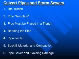
(4) Trench: As per Para IS 783 – 1985 page 373 of the specifications for road bridge work, trench shall be of sufficient width to provide a free working space on either side of the pipe. The working space shall be preferably not less than 150 mm and shall not be more than one third of the dia of pipe.
The minimum clearance between the pipes shall be at least half the diameter of the pipe subject to a minimum of 450 mm. Trench shall be kept free from water until the pipes are installed and the joints have hardened Figure C. Figure C
(5) Jointing: The pipes shall be joined by the collar joints. Collars shall be of R.C.C, 150 mm or 200 mm wide having same strength as the pipes to be joined. Caulking space shall be between 13 to 20 mm according to diameter. Caulking material shall be cement and sand in the ratio of 1:2.
(6) Vent way: Area of pipe = Q/ 2 x Vn where Q = discharge of canal, Vn= normal velocity in the canal. Select the pipe diameter, more than canal F.S.D so that there is partial flow in the pipe. If it requires more than two pipes, go for slab culvert. The partial flowing pipes area is calculated with the help of table given below. a = Ca d2 where a = area of partial flowing pipe Ca = value as per table d = dia of pipe , D = depth of water
(7) The road level should be at the Road level / G.L/ TBL whichever is higher. 300 mm thick P.C.C slab shall be provided over the pipes with 75 mm wearing coat in M 20 with 6 Ф at 200 c/c both ways at top & bottom.