Cisco Router
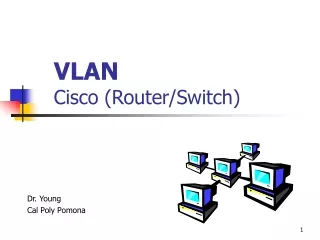
Cisco Router. Cisco Router. The Cisco router IOS Enhanced editing Administrative functions Hostnames Banners Passwords Interface descriptions Verifying your configuration. 2. Cisco Router IOS. Carries network protocols and functions Connects high-speed traffic between devices

Cisco Router
E N D
Presentation Transcript
Cisco Router • The Cisco router IOS • Enhanced editing • Administrative functions • Hostnames • Banners • Passwords • Interface descriptions • Verifying your configuration 2
Cisco Router IOS • Carries network protocols and functions • Connects high-speed traffic between devices • Adds security to control access • Provides scalability for growth • Supplies reliability
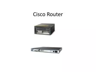
Connecting To A Cisco Router Cisco 2811 Cisco 1841
Bringing up a Router • There are four major phases to the bootup process: 1. Performing the POST 2. Loading the bootstrap program 3. Locating and loading the Cisco IOS software 4. Locating and loading the startup configuration file or entering setup mode
Bringing up a Router 1. Performing the POST • Power-On Self Test (POST) • When the router is powered on, software on the ROM chip conducts the POST. • During this self-test, the router executes diagnostics from ROM on several hardware components including the CPU, RAM, and NVRAM. • After the POST has been completed, the router executes the bootstrap program.
Bringing up a Router 2. Loading the Bootstrap Program • After the POST, the bootstrap program is copied from ROM into RAM. • Once in RAM, the CPU executes the instructions in the bootstrap program. • The main task of the bootstrap program is to locate the Cisco IOS and load it into RAM.
Bringing up a Router 3. Locating and Loading Cisco IOS • The IOS is typically stored in flash memory. • Note: Once the IOS begins to load, you may see a string of pounds signs (#) while the image decompresses. ############################
Bringing up a Router 4. Locating and Loading the Configuration File • Bootstrap program searches for the startup configuration file, known as startup-config, in NVRAM. • file is copied into RAM as the running configuration file, running-config. • If the startup configuration file can not be located, then we enter setup mode.
Memory • ROM : bootstrap • Flash Memory : Cisco IOS • NVRAM : permanent storage for the startup configuration file (startup-config) • If we made changes then we must save it to the NVRAM
Remember • every interface on the router is a member or host on a different IP network. • Each interface must be configured with an IP address and subnet mask of a different network.
Modes • User mode: • Router> • Used mostly to view statistics • Privileged mode: • enable • Router# • Used to view & change router configuration • Global configuration mode. • config terminal or config t • Router (config)#
we use packet tracer program for router configuration in the 3 previous modes . Open Packet Tracer and choose the router :
Double click on the router Choose CLI for router configuration.
Command-Line Interface (CLI) • More flexible than setup mode. • To use the CLI, just say No to entering the initial configuration dialog.
Now we are in the user mode : To know the commands in user mode we use (?) To enter the privilage mode we write: ( enable )
Configuration certain basic tasks are performed including: • Naming the router • Setting passwords • Configuring interfaces • Configuring a banner • Saving changes on a router • Verifying basic configuration and router operations
Configuration • Naming the router • Setting passwords 1- Lone console password to protect the user mode :Console , Telnet 2- Enable password to protect the privilage mode : 3- Secret password for more protection of privilage mode:
Configuration • Banner • Saving changes and restart • or:
Configuration • Interface configuration • To remove password: • To encrypt all passwords:
Using packet tracer in router addressing 1- We connet the figure . • The cables used are : · Straight : between switch, pc and router, switch. · Cross : between switch, switch . · Serial : betweeen the two routers .
Using packet tracer in addressing 2- We put the IP address for each device as the following : • We have in the figure 3 networks :
Using packet tracer in addressing • To distribute the Ip's on the router interfaces we do the following : • Router 0:
Using packet tracer in addressing • For the second router (Router1 ) :
Using packet tracer in addressing • Give each PC it’s IP address: • For PC0 : From IP configuration :
Using packet tracer in addressing • How to ping from PC0 to the default gateway : • For PC0 :
Using packet tracer in addressing We chose command promot and ping on the default gateway :
Homework Exercise 1- Connect the following network using Packet Tracer. 2- Use IP addresses for PC’s as shown in the figure. 3- For each network between two routers make subnetting from the IP address 192.168.4.0/24. What are the 2 networks addresses? IP’s for router interfaces?