Download
1 / 49
490 likes | 600 Vues
This document examines the phenomena of beamstrahlung, focusing on the interactions of particle beams at CESR, KEK, and the International Linear Collider (ILC). It details the distinct characteristics and effects of beamstrahlung compared to synchrotron radiation, influenced by short, powerful magnets and beam-beam interactions. Key parameters affecting luminosity are identified, along with potential beam-beam deflection monitoring strategies. The study further explores radiation properties and new detector concepts aimed at refining measurements and improving understanding of beam dynamics in high-energy physics.

E N D
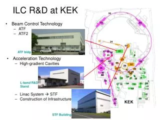
Low energy Beamstrahlung at CESR, KEK and the ILC Giovanni Bonvicini
What is beamstrahlung • The radiation of the particles of one beam due to the bending force of the EM field of the other beam • Many similarities with SR but • Also some substantial differences due to very short “magnet” (L=z/2√2),very strong magnet (3000T at the ILC). Short magnets produce a much broader angular distribution
BBI d.o.f. counting at the ILC • 7 gaussian transverse d.o.f. • 2 beam lengths • At least 4 wake field parameters, and possibly 2 longitudinal • Total 13-15 BBC parameters that may affect the luminosity
Other possible BBI detectors • Beam-beam deflection via BPMs. Limited to 2 quantities by Newton’s 3rd law. Semi-passive device. • Gamma ray beamstrahlung monitor. Almost certainly a powerful device if it can be built with enough pixels, interferes with the beam dump (340kW is dissipated in the dump). It observes at least the total radiation, the centroid of the radiation, and the angular spread (10 d.o.f.) • Pairs spectrometer (105 per BBI). Probably little information as directionality of pair is lost.
Properties of large angle radiation • It corresponds to the near backward direction in electron rest frame (5 degrees at CESR, 2-4 degrees at KEKB) • Lorentz transformation of EM field produces a 8-fold pattern, unpolarized as whole, but locally up to 100% polarized according to cos2(2), sin2(2)
Large angle beamstrahlung power • Total energy for perfect collision by beam 1 is: P0=0.112re3mc2N1N22/(x2z) • Wider angular distribution (compared to quadrupole SR) provides main background separation • CESR regime: exponent is about 4.5 • ILC regime: exponent is very small
If the angle can be considered large and constant… • Assuming (atan(z/)+atan((L-z)/ ) as the field profile, one gets (u=s,c=cos,sin())
The observed radiation is expected to be very red (IR/VIS of order one, 0.02 observed) The observed radiation is expected to have a polarization of order several (1.5-3 observed) The predicted radiation for a 5HEP simulation and sharp acceptance is exactly zero. The backgrounds have a predominant contribution from the halo, which we have just started to describe With a short magnet MC for the quadrupoles…
Large Angle Detector Concept • Radiated power for horizontal and vertical polarizations • Two optic ports are reserved for each direction (E and W) • IR PMT for signal, VIS PMT for background
¼ Set-up principal scheme • Transverse view • Optic channel • Mirrors • PBS • Chromatic mirrors • PMT numeration
Detector parameters of interest • Diffraction limit is 0.1 mrad. Sharp cutoff can be assumed • Optics is double collimator. Has triangular acceptance with max width of 1.7mrad • At IP, accepted spot is about 1cm
Set-up general view • East side of CLEO • Mirrors and optic port ~6m apart from I.P. • Optic channel with wide band mirrors
On the top of set-up • Input optics channel • Radiation profile scanner • Optics path extension volume
The ¼ detector • Input channel • Polarizing Beam Splitter • Dichroic filters • PMT’s assembly • Cooling…
Directionality • Scanning is routinely done to reconfirm the centroid of the luminous spot.
Photomultipliers • IR: R2228, has relatively high noise (3-5 kHz). Has filter at 775 nm • VIS: R6095, almost noise-free, has no filter • Previous IR PMTs R-316-02 were discontinued
Typical rates • At HEP conditions, VIS PMTs (West) will have a rate of about 300kHz (0.1Hz channels are used) and IR PMTs about 6kHz. • In the East, 60kHz and 2kHz. • Expected BMST rates are about 500Hz at the nominal theta
Detector systematics detail • Flashlight calibration measures all relative efficiencies to about 0.3%. Absolute efficiencies of VIS PMT >90%, optical channels assumed to be 75+-25%. • Recurrent electronic noise problems on East side (electrons) • Two major data taking periods in July and December 2007 (about 120 good fills each), with dark noise measured every 8 hours.
Data analysis method • The signal sought ought to increase IR light w.r.t. VIS light when a strong beam is opposite, so IR/VIS=k1+k2Ioppo2 • The method also takes into account possible small variations of the bkg through normalization with VIS light • The expected signal in VIS light is of the order of 10-4 of the rate and can be safely ignored • Runs are minimally selected (continuous beams for at least 600 seconds) with chi square and dark noise (cleaning) cuts later to take care of noisy ones
Natural variability of machine provided crucial evidence • In July, relatively high e+ current and relatively low e- current. In December, currents are more balanced, providing a stronger expected BMST signal • In July, e- beam was smaller than e+. In December, the reverse was true. Differing polarizations expected
Main results page • Signal(x) strongly correlated to I+I-2 • Signal strongly polarized according to ratios of vertical sigmas • Total rates consistent with expectations at 10.3 mrad
What went wrong • The beams ended up being longer than design • The primary mirrors are attached to the beam pipe. We found a best correction of -0.2mrad for the West PMTs and +1.1mrad for the East (using VIS only). This virtually killed the East signal • The tails of the beam decrease in intensity during a fill
What went wrong (II) • The fractional tails of a beam will typically decline during a shift • The decline much more pronounced in the East (electrons) due to larger BBI, wider beam, larger angle, and bunch length
We have been able to explain qualitatively ALL the effects seen in our apparatus ALL major cross checks on the signal are successful. In particular, polarization effects appear to be proven We are currently trying to establish the beam tail characterization using only the VIS data Followed by one big global fit (including bunch length, sigma_x, crossing angle, etc.) Publication of NIM and PRSTAB papers Where we are
The first generation Large Angle Beamstrahlung detector was successful, but… This technique is dominated by systematic errors, therefore its only figure of merit is S/B In order to make this technique into a useful monitor, three conditions must be met: - S/B >>1 (it was 0.03-0.06 at CESR). We can tolerate lower S/B if the tails are proven to be constant during a fill - Much more beam data acquired A device that can monitor the beam halo directly Summary
Signal and background at KEKB • KEKB is the best place where to pursue this technique further, due to short bunch length • Signal at KEK (assume 10 mrad observation): the signal scales with (N3/2x2z)*exp(-(z2/2) 2) - about 100 times higher specific signal • The halo, assuming to be dominated by the BBI, scales like (N/) - close to CESR values. If it is dominated by the residual gas pressure, it should be much more constant and therefore subtractable • Other improvements at KEK (cmp to CESR): beams cross quadrupoles near axis (less background), there is no parasitic BBI, and therefore no shifts in the crossing angle
Fringe map of quads BPMs Background/pressure monitors sx and sz from CLEO directly in the database What information would have been useful
KEKB concept for the detector • 2 viewports at +-90 degrees: minimal backgrounds, insensitive of beam motion, insensitive of beam pipe alignment • Look at radiation in 4 or more bands: e.g., < 350nm, 400nm<<450nm, 500nm<<550nm, 600nm<<650nm • (this is assuming one uses only PMTs R6095)
Rates per bunch crossing (1<<2mrad): about 20000 at nominal conditions Sigma_y’ is about 0.01mrad at the ILC. Tails unknown Rates per bunch cross, (5<<6mrad): about 80 at nominal conditions Backgrounds should be very close to zero at this angle ILC Concept (II)
Beam pipe shielding • Beam pipe effects are important for long magnets (Heifets, Mikhailichenko, SLAC-AP-083) • However at the ILC R is of order 0.5 meters and coherent radiation will be present in the millimeter range
Can we see this effect at current accelerators? • The best place is KEKB (d=3cm, z =6mm) • But, need the fraction of coherent power generated within the beam pipe. Fortunately, a paper by Hoffstatter, Sagan et al. (not yet published) has produced a code to calculate just that • Try to detect TM waveguide modes at first BPM (M. Billings) with single bunches offset by 4y. Time, frequency, beam-beam offset and N4 signatures available
Conclusions • Large angle Beamstrahlung seen at CESR • Its main features confirmed • Major sources of systematics found • Interesting for ILC R&D in an area of strong need
Coherent enhancement at the ILC (dynamic beams, complete coherence)
CB coherent enhancement (vacuum, no angular divergence) • C=P(CB)/P(IB) • C(,)=N exp(-(2z / )2) (G. Bonvicini, unpublished) • Angular effects reduce radiation by O ((div/rad)2) (not important at CESR, factor of 100 at the ILC). This gives a maximum CB average power at the ILC in the neighborhood of 1W (0.1GW peak)
IB power (stiff beams) • CB largely leaves the spectrum unaffected and adds a factor N1
Coherent beamstrahlung • Coherent synchrotron radiation has been observed many times for very short beams • Coherence condition is >z (there is also a transverse coherence condition, negligible here) • A similar situation arises when beams are separated - coherent beamstrahlung • Coherent enhancement always proportional to N