Download
1 / 69
690 likes | 1.26k Vues
9/12/2012. Part Programming. APT (Automatically Programmed Tool) is a software compiler for simplifying numerical control Programming. Developed by MIT in 1959APT is the most widely used processor. 9/12/2012. APT. APT (Automatically Programmed Tool) is a software compiler for simplifying numer

E N D
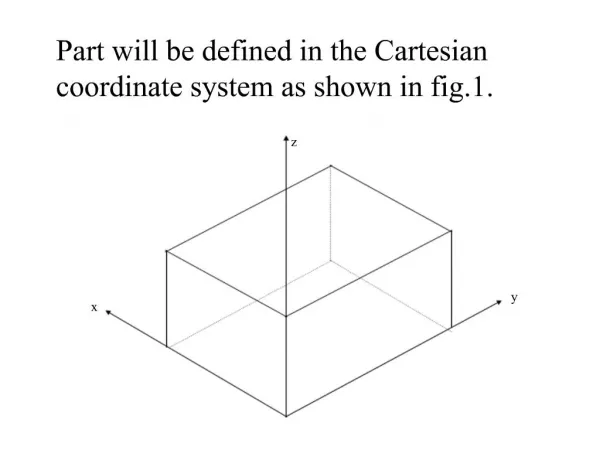
1. Part will be defined in the Cartesian coordinate system as shown in fig.1.
2. 9/12/2012
3. 9/12/2012
4. 9/12/2012
5. 9/12/2012
6. The general format for geometric statements is:
<Symbol> = Geometric Type/ Definitional Modifiers
7. Point (POINT) PTA = POINT/ 3,4,5
8. Point (POINT) PTB = POINT/ INTOF, LIN1, LIN2
9. Point (POINT) PTD = POINT/ YSMALL, INTOF, LIN3, C1
PTD = POINT/ XSMALL, INTOF, LIN3, C1
PTC = POINT/ YLARGE, INTOF, LIN3, C1
PTC = POINT/ XLARGE, INTOF, LIN3, C1
10. Point (POINT) PTE = POINT/ YLARGE, INTOF, C1, C2
PTE = POINT/ XLARGE, INTOF, C1, C2
PTF = POINT/ YSMALL, INTOF, C1, C2
PTF = POINT/ XSMALL, INTOF, C1, C2
11. Point (POINT) PT7 = POINT/ CENTER, C6
12. Point (POINT) PT11 = POINT/ P63, RADIUS, 7.3, ATANGLE, 27
13. Pattern (PATERN) <Symbol> = PATERN/ LINEAR, <start>, <end>, <n>
PATG = PATERN/ LINEAR, P16, PT3, 6
PTZ = POINT/ PATG, 5
14. Pattern (PATERN) <Symbol> = PATERN/ COPY, PAT1, ON, PAT2
PAT7 = PATERN/ COPY, PAT1, ON, PAT2
15. Pattern (PATERN) SAME: after the pattern designator will force that pattern sequence no.s to follow their original sequence.
PAT8 = PATERN/ COPY, PAT1, ON, PAT2, SAME
16. Pattern (PATERN) UNLIKE: the sequence of points will be reversed on the 2nd cycle from that of the 1st & the 3rd will be reversed from the second & so on.
PAT11 = PATERN/ COPY, PAT1, ON, PAT2, UNLIKE
17. Pattern (PATERN) PAT12 = PATERN/ COPY, PAT1, UNLIKE, ON, PAT2
18. Line (LINE) LIN1 = LINE/ P1, P2
19. Line (LINE) LIN4 = LINE/ PT6, 15, -30, 3
20. Line (LINE) LIN10 = LINE/ 20, 3.5, 0.2, 31, 6.2, 1.3
21. Line (LINE) L12 = LINE/ PT4, ATANGLE, 20, XAXIS
L14 = LINE/ PT1, ATANGLE, 40
L15 = LINE/ 32, -3, 2, ATANGLE, -15, XAXIS
L16 = LINE/ PT3, ATANGLE, 40, YAXIS
22. Line (LINE) LIN = LINE/ POINT, SLOPE, NUMERICAL VALUE, LINE
23. Line (LINE) LIN = LINE/ POINT, ATANGL, ANGLE (in degrees), LINE
24. Line (LINE) LIN = LINE/ SLOPE, SLOPE VALUE, INTERC, MODIFIER, d
where the slope value is y/x. The modifier options are [XAXIS, YAXIS], and d is the corresponding intercept value on the selected axis (i.e., modifier).
25. Line (LINE) LIN = LINE/ ATANGL, DEGREES, INTERC, MODIFIER, d
The modifier options are [XAXIS, YAXIS], and d is the corresponding intercept value on the selected axis (i.e., modifier).
26. Line (LINE) The LEFT & RIGHT modifier indicates whether the line is at the left or right tangent point, depending on how one looks at the circle from the point.
L1 = LINE/ PT51, LEFT, TANTO, C11
27. Line (LINE) L2 = LINE/ PT51, RIGHT, TANTO, C11
L3 = LINE/ PT40, RIGHT, TANTO, C11
L4 = LINE/ PT40, LEFT, TANTO, C11
28. Line (LINE) L6 = LINE/ LEFT, TANTO, C3, LEFT, TANTO, C4
29. Line (LINE) L7 = LINE/ LEFT, TANTO, C3, RIGHT, TANTO, C4
L7 = LINE/ LEFT, TANTO, C4, RIGHT, TANTO, C3
30. Line (LINE) L8 = LINE/ RIGHT, TANTO, C3, LEFT, TANTO, C4
31. Line (LINE) L9 = LINE/ RIGHT, TANTO, C3, RIGHT, TANTO, C4
L9 = LINE/ LEFT, TANTO, C4, LEFT, TANTO, C3
32. Line (LINE) LN3 = LINE/ PNT6, PARLEL, LN15
LN4 = LINE/ PNT5, PERPTO, LN13
33. Plane (PLANE) LN5 = LINE/ INTOF, PLAN1, PLAN2
34. Plane (PLANE) PLAN10 = PLANE/ PT6, PT12, PT15
35. Plane (PLANE) PLAN14 = PLANE/ PT4, PARLEL, PLAN10
PLAN14 = PLANE/ PARLEL, PLAN10, YSMALL, 3.0
36. Circle (CIRCLE) C1 = CIRCLE/ 3, 6, 5, 4.3
C1 = CIRCLE/ CENTER, PT3, RADIUS, 4.3
37. Circle (CIRCLE) C3 = CIRCLE/ CENTER, PT6, TANTO, LN4
C7 = CIRCLE/ CENTER, PT8, PT5
38. Circle (CIRCLE) C3 = CIRCLE/ YLARGE, LN6, XLARGE, LN4, RADIUS, 2.0
C3 = CIRCLE/ XLARGE, LN6, YSMALL, LN4, RADIUS, 2.0
39. Circle (CIRCLE) C1 = CIRCLE/ YLARGE, LN6, YLARGE, LN4, RADIUS, 3.0
40. Circle (CIRCLE) C2 = CIRCLE/ XSMALL, LN6, XSMALL, LN4, RADIUS, 1.5
C2 = CIRCLE/ YLARGE, LN4, YSMALL, LN6, RADIUS, 1.5
41. Cylinder (CYLNDR) <Symbol> = CYLNDR/ <axis modifier>, TANTO, <1st plane>, <axis modifier>, TANTO, <2nd plane>, RADIUS, <radius value>
The axis modifier depends on the relationship of the cylinder center point to the tangent point of the plane the modifier precedes.
42. Cylinder (CYLNDR) CYL3 = CYLNDR/ XLARGE, TANTO, PLAN5, YSMALL, TANTO, PLAN10, RADIUS, 2.0
43. Geometry Example The top view of a plate is shown in the following figure. The outer shape of this plate is to be milled & the grid holes drilled. It is therefore necessary to define the geometry of the part, i.e. its outer shape & the location of the holes.
44. Geometry Example PT1 = POINT/ 4, 5, 0
PT2 = POINT/ 5, 4.6, 0
PT3 = POINT/ 8, 4.6, 0
PT4 = POINT/ 8, 3.2, 0
PT5 = POINT/ 9, 3.75, 0
C1 = CIRCLE/ CENTER, PT5, RADIUS, 1.25
PT6 = POINT/ 4, 1, 0
L1 = LINE/ PT1, LEFT, TANTO, C1
L3 = LINE/ PT1, PT6
L2 = LINE/ PT6, RIGHT, TANTO, C1
PLAN1 = PLANE/ PT1, PT2, PT3
PLAN2 = PLANE/ PARLEL, PLAN1, ZSMALL, 0.5
PTN1 = PATERN/ LINEAR, PT2, PT3, 4
PTN2 = PATERN/ LINEAR, PT3, PT4, 3
PTN3 = PATERN/ COPY, PTN2, UNLIKE, ON, PTN1
45. The Machining Plan Point- to- point: refers to operations requiring fast movement (straight- line motions) to a point followed by a manufacturing operation at that point.
FROM/ <point location>: denotes that the point location is a starting point for the tool, with the end of the tool at that point.
GOTO/ <point location>: refers to a rapid, straight- line move to the point location indicated.
GODELTA/ <coordinate increments>: commands the tool to move incremental distance from the current position.
46. The Machining Plan P1 = POINT/ 1.0, 2.7, 0.1
P2 = POINT/ 2.0, 2.7, 0.1
P3 = POINT/ 1.0, 2.0, 0.1
47. The Machining Plan FROM/ PO
GOTO/ P1
GODELTA/ 0, 0, -0.8
GODELTA/ 0, 0, 0.8
GOTO/ P2
GODELTA/ 0, 0, -0.8
GODELTA/ 0, 0, 0.8
GOTO/ P3
GODELTA/ 0, 0, -0.8
GODELTA/ 0, 0, 0.8
GOTO/ PO
48. The Machining Plan MACROS: A macro is a single computer instruction that stands for a given sequence of instructions.
<name> = MACRO/ <possible parameters><sequence of instructions>
TERMAC
The macro can be used any time in the APT program by
CALL macro name (, list of parameters)
49. The Machining Plan PO = POINT/ 0, 4, 0.1
DELTA = MACRO/ DX, DY
GOTO/ DX, DY, ________
GODELTA/ _______, ________, ________
GODELTA/ _______, ________, ________
TERMAC
FROM/ PO
CALL DELTA/ DX = _______, DY = _______
CALL DELTA/ DX = _______, DY = _______
CALL DELTA/ DX = _______, DY = _______
GOTO/ PO
50. The Machining Plan: Contouring:
Part surface: the surface on which the end of the tool is riding.
Drive surface: the surface against which the edge of the tool rides.
Check surface: a surface at which the current tool motion is to stop.
51. The Machining Plan
52. The Machining Plan
53. The Machining Plan TANTO :
A: GO/ TO, L1, TO, PL2, TANTO, C1
B: GO/ PAST, L1, TO, PL2, TANTO, C1
54. The Machining Plan Motion commands:
GOLFT/ : Move left along the drive surface
GORGT/ : Move right along the drive surface
GOUP/ : Move up along the drive surface
GODOWN/ : Move down along the drive surface
GOFWD/ : Move forward from a tangent position
GOBACK/ : Move backward from a tangent position
55. The Machining Plan GORGT/ <drive surface>, <check surface>
Start ? A? B ? C ? D ? E ? Start
FROM/ START
GO/ TO, L1, TO, PL1, ON, L3
GORGT/ L1, TANTO, C1
GOFWD/ C1, TANTO, L2
GOFWD/ L2, PAST, L3
GOLFT/ L3, PAST, L1
GOTO/ START
56. Machining Specifications Postprocessor commands for a particular machine tool are:
MACHIN/ : used to specify the machine tool and call the postprocessor for that tool:
MACHIN/ DRILL, 3
COOLNT/ : allows the coolant fluid to be turned on or off:
COOLNT/ MIST
COOLNT/ FLOOD
COOLNT/ OFF
57. Machining Specifications FEDRAT/ : specifies the feed rate for moving the tool along the part surface in inches per minute:
FEDRAT/ 4.5
SPINDL/ : gives the spindle rotation speed in revolutions per minute:
SPINDL/ 850
TURRET/ : can be used to call a specific tool from an automatic tool changer:
TURRET/ 11
58. Machining Specifications TOLERANCE SETTING: Nonlinear motion is accomplished in straight-line segments, and INTOL/ and OUTTOL/ statements dictate the number of straight-line segments to be generated.
INTOL/ 0.0015
OUTTOL/ 0.001
59. Machining Specifications
60. Machining Specifications PARTNO: identifies the part program and is inserted at the start of the program.
CLPRINT: indicates that a cutter location printout is desired.
CUTTER: specifies a cutter diameter for offset (rough versus finish cutting). If a milling cutter is 0.5 in. in diameter and we have
CUTTER/ 0.6
then the tool will be offset from the finish cut by 0.05 in.
61. Machining Specifications FINI: specifies the end of the program.
62. APT Contouring Example PARTNO P1534
MACHIN/ MILL, 4
CLPRINT
OUTTOL/ 0.0015
P0 = POINT/ 0, 0, 1.1
P1 = POINT/ 1, 1, 0.5
P2 = POINT/ 4, 3.5, 0.5
P3 = POINT/ 5.85, 2.85, 0.5
PL1 = PLANE/ P1, P2, P3
PL2 = PLANE/ PARLEL, PL1, ZSMALL, 0.5
P4 = POINT/ 5, 1.85, 0.5
P5 = POINT/ 2, 2.5, 0.5
C1 = CIRCLE/ CENTER, P4, RADIUS, 0.85
C2 = CIRCLE/ CENTER, P5, RADIUS, 1.0
L1 = LINE/ P1, RIGHT, TANTO, C1
L2 = LINE/ P3, LEFT, TANTO, C1
L3 = LINE/ P2, P3
L4 = LINE/ P2, RIGHT, TANTO, C2
L5 = LINE/ P1, LEFT, TANTO, C2
MILLS = MACRO/ CUT, SSP, FRT, CLT
CUTTER/ CUT
63. APT Contouring Example FEDRAT/ FRT
SPINDL/ SSP
COOLNT/ CLT
FROM/ P0
GO/ TO, L1, TO, PL2, ON, L5
GORGT/ L1, TANTO, C1
GOFWD/ C1, TANTO, L2
GOFWD/ L2, PAST, L3
GOLFT/ L3, PAST, L4
GOFWD/ L4, TANTO, C2
GOFWD/ C2, TANTO, L5
GOFWD/ L5, PAST, L1
COOLNT/ OFF
GOTO/ P0
TERMAC
TURRET 4
CALL/ MILLS, CUT = 0.52, SSP = 600, FRT = 3.0, CLT = FULL
TURRET/ 6
CALL/ MILLS, CUT = 0.5, SSP = 900, FRT = 2.0, CLT = FULL
SPINDL/ 0
END
FINI
64. Complete APT Program P0 = POINT/ 0, -2, 0
P1 = POINT/ 0.312, 0.312, 0
P2 = POINT/ 4, 1, 0
C1 = CIRCLE/ CENTER, P1, RADIUS, 0.312
C2 = CIRCLE/ CENTER, P2, RADIUS, 1
L2 = LINE/ RIGHT, TANTO, C2, RIGHT, TANTO, C1
L1 = LINE/ LEFT, TANTO, C2, LEFT, TANTO, C1
PL1 = PLANE/ P0, P1, P2
MILL = MACRO/ DIA
FROM/ P0
GO/TO, L1, TO, PL1, TO, C2
GOLFT/ L1, PAST, C1
GOFWD/ C1, PAST, L2
GOFWD/ L2, PAST, C2
GOFWD/ C2, PAST, L1
GOTO/ P0
TERMAC
CALL MILL / DIA = 0.70
END
FINI
65. Complete APT Program P0 = POINT/ -1, -1
P1 = POINT/ 0, 0
P2 = POINT/ 3, 0
P3 = POINT/ 4, 0
P4 = POINT/ 6.5, 5.5
C1 = CIRCLE/ CENTER, P3, RADIUS, 1
L0 = LINE/ P1, P2
L1 = LINE/ (POINT/ 5, 1), LEFT, TANTO, C1
L2 = LINE/ (POINT/ 7, 1), PERPTO, L1
C2 = CIRCLE/ CENTER, P4, RADIUS, 0.5
L3 = LINE/ (POINT/ 7, 1), RIGHT, TANTO, C2
L4 = LINE/ (POINT/ 5, 6), LEFT, TANTO, C2
C3 = CIRCLE/ CENTER, (POINT/ 4, 6), (POINT/ 3, 6)
L5 = LINE/ (POINT/ 0, 6), (POINT/ 3, 6)
L6 = LINE, P1, PERPTO, L5
PL1 = PLANE/ P1, P2, P3
MILL = MACRO/ DIA
CUTTER/ DIA
66. Complete APT Program GORGT/ L0, TO, C1
GORGT/ C1, TO, L2
GORGT/ L2, PAST, L3
GOLFT/ L3, TANTO, C2
GOFWD/ C2, TANTO, L4
GOFWD/ L4, PAST, C3
GOLFT/ C3, PAST, L5
GOLFT/ L5, PAST, L6
GOLFT/ L6, PAST, L0
TERMAC
FROM/ P0
GO/ TO, L0, TO, PL1, TO, L6
COOLNT/ ON
FEDRAT = 3
SPINDL = 400
CALL MILL/ DIA = 0.95
COOLNT/ OFF
END
FINI
67. APT Program MACHIN/ MILL
P0 = POINT/ 0, 0, 3
P1 = POINT/ 1, 0
L1 = LINE/ P1, SLOPE, 0
L2 = LINE/ P1, SLOPE, 90
L3 = LINE/ PARLEL, L1, YLARGE, 2
L4 = LINE/ (POINT/ 4, 2), SLOPE, 1, L3
L5 = LINE/ (POINT/ 6, 4), ATANGL, 270, L4
L6 = LINE/ (POINT/ 10, 0), PEPTO, L3
P2 = POINT/ INTOF, L3, L4
P3 = POINT/ INTOF, L4, L5
P4 = POINT/ INTOF, L5, L3
PL = PLANE/ P1, P2, P3
CUTTER/ 60
TOLER/ 0.1
SPINDL/ 200
COOLNT/ ON
FEDRAT/ 20
68. APT Program MACHIN/ MILL
P0 = POINT/ 0, 0, 3
P1 = POINT/ 1, 0
L1 = LINE/ P1, SLOPE, 0
L2 = LINE/ P1, SLOPE, 90
L3 = LINE/ PARLEL, L1, YLARGE, 2
L4 = LINE/ (POINT/ 4, 2), SLOPE, 1, L3
L5 = LINE/ (POINT/ 6, 4), ATANGL, 270, L4
L6 = LINE/ (POINT/ 10, 0), PEPTO, L3
P2 = POINT/ INTOF, L3, L4
P3 = POINT/ INTOF, L4, L5
P4 = POINT/ INTOF, L5, L3
PL = PLANE/ P1, P2, P3
CUTTER/ 60
TOLER/ 0.1
SPINDL/ 200
COOLNT/ ON
FEDRAT/ 20
69. APT Program FROM/ P0
GOTO/ L1, TO, PL, TO, L2
GOFWD/ P1, PAST, L3
GORGT/ L3, TO, P2
GOLFT/ P2, TO, P3
GORGT/ P3, TO, P4
GORGT/ P4, PAST, L6
GORGT / L6, PAST, L1
GORGT / L1, TO, P1
COOLNT/ OFF
END
FINI