PROSTHETIC PROCEDURE MANUAL AR SYSTEM
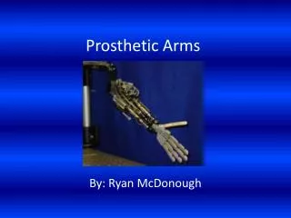
PROSTHETIC PROCEDURE MANUAL AR SYSTEM. CEMENTED RESTORATION. Impression Copings. Cemented Abutment. Pick-up. Set Screw. Implant Analog. Angled Abutment. Transfer. IMPRESSION COPINGS Implant Level – Pick-up. 1.2mm Hex Driver. Guide Pin. Engaging.

PROSTHETIC PROCEDURE MANUAL AR SYSTEM
E N D
Presentation Transcript
CEMENTED RESTORATION Impression Copings Cemented Abutment Pick-up Set Screw Implant Analog Angled Abutment Transfer
IMPRESSION COPINGSImplant Level – Pick-up 1.2mm Hex Driver Guide Pin Engaging • Implant level impression, pick-up impression coping (open tray technique) • Impression coping is packaged with corresponding guide pin • Use 1.2mm Hex driver to assemble/ disassemble
IMPRESSION COPINGSImplant Level – Transfer 1.2mm Hex Driver Guide Pin Engaging • Implant level impression, transfer impression coping (closed tray technique) • Impression coping is packaged with corresponding guide pin • Use 1.2mm Hex driver to assemble/ disassemble
CEMENTED ABUTMENT 1.2mm Hex Driver DIAMETER HEIGHT CUFF Engaging Fastening torque 30 Ncm
ANGLED ABUTMENT 1.2mm Hex Driver DIAMETER HEIGHT CUFF Engaging • Options of 15 degrees and 25 degrees • Angled Abutments are packaged alongside corresponding set screw • Fastening torque 30 Ncm
SET SCREW DIAMETER LENGTH • Cemented Abutment screw is 10mm long • Angled Abutments screw is 8mm long • Set screws are packaged along with corresponding abutment
CLINICAL PROCESSFixing Impression Copings (1/3) • View of patient’s mouth
CLINICAL PROCESSFixing Impression Copings (2/3) • Remove healing abutment / cover screw with 1.2mm Hex Driver • Insert impression coping inside corresponding implant connection
CLINICAL PROCESSFixing Impression Copings (3/3) • Fasten impression coping with corresponding guide pin • Tighten guide pin with 1.2mm hex driver
CLINICAL PROCESSTaking The Impression (1/6) • Apply the light impression material on corresponding site of oral cavity
CLINICAL PROCESSTaking The Impression (2/6) • Pour the heavy impression material inside the impression tray
CLINICAL PROCESSTaking The Impression (3/6) • Position tray for impression taking • Apply pressure until top part of guide pin appears • wait for impression material to set • Transfer impression copings will require prefabricated tray • Pick-up impression copings will require previously customized tray
CLINICAL PROCESSTaking The Impression (4/6) • Remove guide pin
CLINICAL PROCESSTaking The Impression (5/6) • Check tray for impression errors / success
CLINICAL PROCESSTaking The Impression (6/6) • Replace healing abutment / cover screw in corresponding site
LABORATORY PROCESS1. Fixing Analogs & Making Artificial Gum (1/4) • Fix analogs on corresponding impression coping
LABORATORY PROCESS1 - Fixing Analogs & Making Artificial Gum (2/4) • Apply (Spray) separating product on impression areas
LABORATORY PROCESS1. Fixing Analogs & Making Artificial Gum (3/4) • Apply artificial gum product on intervention area • Wait for product to dry
LABORATORY PROCESS1. Fixing Analogs & Making Artificial Gum (4/4) • Trim gum
LABORATORY PROCESS2. Master Modeling (1/3) • Prepare (mix) the stone
LABORATORY PROCESS2. Master Modeling (2/3) • Pour the mixed stone inside the impression
LABORATORY PROCESS2. Master Modeling (3/3) • Master model finishing work
LABORATORY PROCESS3. Abutment Milling (1/5) • Fix the abutment to the analog
LABORATORY PROCESS3. Abutment Milling (2/5) • Abutment Milling (Step 1)
LABORATORY PROCESS3. Abutment Milling (3/5) • Abutment Milling (Step 2)
LABORATORY PROCESS3. Abutment Milling (4/5) • Abutment Milling (Step 3)
LABORATORY PROCESS3. Abutment Milling (5/5) • Post Milling
LABORATORY PROCESS4. Pattern Resin & Wax-Up (2/3) • Wax-up process (Steps 1 & 2)
LABORATORY PROCESS4. Pattern Resin & Wax-Up (3/3) • Wax-up process (Steps 3 & 4)
LABORATORY PROCESS5. Sprewing (1/2) • Sprewing (Step 1)
LABORATORY PROCESS5. Sprewing (2/2) • Sprewing (Step 2)
LABORATORY PROCESS6. Investment (1/2) • Investment (Step 1)
LABORATORY PROCESS6. Investment (2/2) • Burn out (Step 3) • Investment (Step 2)
LABORATORY PROCESS7. Casting • Cast and extract cast structure
LABORATORY PROCESS8. Adaptation & Metal Trimming • Check cast structure for adaptation on master model
LABORATORY PROCESS10. Transfer Jig (1/2) • Make the transfer Jig
LABORATORY PROCESS10. Transfer Jig (2/2) • Place the abutment(s) inside the oral cavity by using the transfer jig