Understanding Input/Output Modules and Techniques in Computing Systems
This guide explores the essential functions and techniques of Input/Output (I/O) modules in computing. It covers the need for I/O modules as intermediaries between the CPU, memory, and peripheral devices. Key topics include the generic model of I/O modules, various external devices, and I/O techniques such as programmed I/O, interrupt-driven I/O, and direct memory access (DMA). The document also discusses addressing and mapping I/O devices, as well as the challenges of handling interrupts and optimizing data transfer.

Understanding Input/Output Modules and Techniques in Computing Systems
E N D
Presentation Transcript
Input/Output Problems • Wide variety of peripherals • Delivering different amounts of data • At different speeds • In different formats • All slower than CPU and RAM • Need for I/O modules 1
Input/Output Module • Interface to CPU and Memory • Interface to one or more peripherals • I/O module – I/O adapter (equal concepts) 2
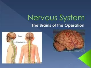
External Devices • Human readable • Screen, printer, keyboard • Machine readable • Monitoring and control • Communication • Modem • Network Interface Card (NIC) 4
I/O Module Function • Control & Timing • CPU Communication • Device Communication • Data Buffering • Error Detection 6
I/O Steps • CPU checks I/O module device status • I/O module returns status • If ready, CPU requests data transfer • I/O module gets data from device • I/O module transfers data to CPU • Variations for output, DMA, etc. 7
Input Output Techniques • Programmed • Interrupt driven • Direct Memory Access (DMA) They differ in the way in which I/O module informs CPU that the peripheral operation has finished. 9
Programmed I/O • CPU has direct control over I/O • Sensing status • Read/write commands • Transferring data • CPU waits for I/O module to complete operation • Wastes CPU time 11
Programmed I/O - detail • CPU requests I/O operation • I/O module performs operation • I/O module sets status bits • CPU checks status bits periodically • I/O module does not inform CPU directly • I/O module does not interrupt CPU • CPU may wait or come back later 12
I/O Commands • CPU issues address • Identifies module (& device if >1 per module) • CPU issues command • Control - telling module what to do • e.g. seek operation on disk • Test - check status • e.g. power? Error? • Read/Write • Module transfers data via buffer from/to device 13
Addressing I/O Devices • Under programmed I/O data transfer is very like memory access (CPU viewpoint) • Each device given unique identifier • CPU commands contain identifier (address) 14
I/O Mapping • Memory mapped I/O • Devices and memory share an address space • I/O looks just like memory read/write • No special commands for I/O • Large selection of memory access commands available • Isolated I/O • Separate address spaces • Need I/O or memory select lines • Special commands for I/O • Limited set 15
Interrupt Driven I/O • Overcomes CPU waiting • No repeated CPU checking of device • I/O module interrupts when ready 16
Interrupt Driven I/OBasic Operation • CPU issues read command • I/O module gets data from peripheral whilst CPU does other work • I/O module interrupts CPU • CPU requests data • I/O module transfers data 17
CPU Viewpoint • Issue read command • Does other work • Check for interrupt at end of each instruction cycle • If interrupted:- • Save context (registers) • Process interrupt • Fetch data & store 18
Design Issues • How do you identify the module issuing the interrupt? • How do you deal with multiple interrupts? • i.e. an interrupt handler being interrupted 20
Identifying Interrupting Module (1) • Different line for each module • PC • The number of devices is limited. • Software poll • CPU asks each module in turn • Slow 21
Multiple Interrupts • Each interrupt line has a priority • Higher priority lines can interrupt lower priority lines • If bus mastering only current master can interrupt 22
ISA Bus Interrupt System • ISA bus chains two 8259As together • Link is via interrupt 2 • Gives 15 lines • 16 lines less one for link • IRQ 9 is used to re-route anything trying to use IRQ 2 • Backwards compatibility • Incorporated in chip set 23
Direct Memory Access • Interrupt driven and programmed I/O require active CPU intervention • Transfer rate is limited • CPU is tied up • DMA is the answer 25
DMA Function • Additional Module (hardware) on bus • DMA controller takes over from CPU for I/O 26
DMA Operation • CPU tells DMA controller:- • Read/Write • Device address • Starting address of memory block for data • Amount of data to be transferred • CPU carries on with other work • DMA controller deals with transfer • DMA controller sends interrupt when finished 28
I/O Channels • I/O devices getting more sophisticated • e.g. 3D graphics cards • CPU instructs I/O controller to do transfer • I/O controller does entire transfer • Improves speed • Takes load off CPU • Dedicated processor is faster 29