Download
1 / 33
330 likes | 455 Vues
Join Russell Cooper from Juniper Networks at APRICOT 2011 to explore the challenges of server virtualization in data center networks. This session will highlight the evolution of server virtualization, addressing market drivers, limitations of legacy systems, and the need for simplification and enhanced services. By demonstrating a standards-based approach, attendees will learn how to improve performance and manageability in a virtualized environment, leading to better resource utilization and agility.

E N D
Networking Solutions for A Server Virtualization Environment APRICOT 2011 Russell Cooper russ@juniper.net
What you will get from this session • 1. Talk: about challenges Server Virtualization technologies brings for the data center networks. • 2. Demonstrate: standards based approach, where available, to improve the experience and economics in a virtualized environment.
Agenda • Market Drivers • Limitations of legacy network • Solutions • Simplification • Infrastructure • Enhanced services • Summary
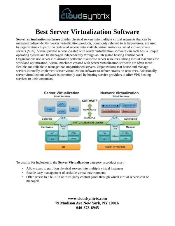
The evolution of Server Virtualization PHASE 1 PAST PHASE 2 FUTURE Server Consolidation Business Agility Guiding Principle: Improve utilization of physical resources Guiding Principle: : Improve utilization of a pool of resources • Driver: • Power and space • Improvements in server utilization • Savings • Driver: • Adapt quickly to new demands • Heightened compliance & security • Better disaster management • Cloud Based Computing Models Network had no role Network has a huge role
Legacy networks restrict agility Too Many Devices to Manage Additional virtual switches COMPLEX: LACK OF ADDITIONAL SERVICES: INFRASTRUCTURE: POOR PERFORMANCE Multiple layers Across North-South path MOBILITY: North-south path Scale & scope of L2 adjacencies Across sites VM3 VM2 VM3 VM2 VM1 PROPRIETARY: Pre-standard protocols SECURITY:Silo’ed , unavailable across domains Intra-VM traffic NIC NIC MANAGEABILITY:Orchestration between the physical and virtual network VM1 SERVER 1 SERVER 2
Network Simplification for supporting Server Virtualization Too Many Devices to Manage Additional virtual switches COMPLEX: SIMPLIFICATION LACK OF ADDITIONAL SERVICES: ENHANCED SERVICES NEEDED INFRASTRUCTURE THAT IS: INFRASTRUCTURE: POOR PERFORMANCE Multiple layers Across North-South path MOBILITY: North-south path Scale & scope of L2 adjacencies Across sites HIGH PERFORMANCE MOBILITY VM3 VM3 VM2 VM2 VM1 PROPRIETARY: Pre-standard protocols Interoperability Lock-in SECURITY:Silo’ed , unavailable across domains Intra-VM traffic OPEN, STANDARDS BASED SECURITY NIC NIC MANAGEABILITY:Orchestration between the physical and virtual network MANAGEABILITY VM1 SERVER 1 SERVER 2
Network Device Clustering SIMPLIFICATION Fewer devices to manage: 44 -> 4 BEFORE AFTER
Technology approaches Control Plane Unification L2 Table Synch • Facts • Simplifyoperations • Behaves as a single nodeboth at L2 & L3 layers so itinheritsallbenefitsfound in L2 TableSynchapproach • Facts • Distributed link aggregation (LAG) plus some L2/L3 protocolsenhancementstominimizeinterchassis link load Multiple Devices – Enhanced Protocols Multiple Devices – One Control Plane
Open standards based SIMPLIFICATION ENHANCED SERVICES NEEDED INFRASTRUCTURE THAT IS: HIGH PERFORMANCE MOBILITY OPEN, STANDARDS BASED SECURITY MANAGEABILITY
Communication between the Virtual machines NIC NIC NIC VM2 VM1 VM3 VM2 VM1 VM3 VM2 VM1 VM3 In the hypervisor vendor’s switch(e.g.VM Ware vSwitch) 2. In the NIC 3. In the existing external physical switch (VEPA)
Comparing VEPA AND VEB Network services in hardware Physical switch NIC NIC Hypervisor/software switch Network services in software VM2 VM1 VM3 VM2 VM1 VM3 Virtual Ethernet Port Aggregator (VEPA) North – South optimized Full functioned hardware switch Virtual Ethernet Bridge (VEB) East – West optimized Limited function software switch
Comparison of options 1 2 3 vSwitch NIC VEPA Switching done in Software Hardware Hardware Feature Richness Very Low Low High Low – comes in- built with hypervisor Low - simple software upgrade Customer’s Time to adopt solution Unknown Customers’ Cost to adopt Low – comes with hypervisor Free - software upgrade Unknown Compatibility with any existing network Yes Unknown Yes Very Low Latency for switching Very Low Low Industry support (standards based) NA Unknown Yes Virtual switching managed by Network Admin Server admin Unknown
VEPA • Virtual Ethernet Port Aggregator • Uses external physical network for intra-server VM to VM communication • It’s an evolving open standard IEEE 802.1Qbg / 802.1Qbh • Supported by almost all the major IT vendors • For more information http://www.ieee802.org/1/files/public/docs2009/new-bg-thaler-par-1109.pdf http://www.ieee802.org/1/pages/802.1bg.html NIC VM2 VM1 VM3 VEPA brings the evolved Ethernet functionality to virtual networking
Top 3 benefits of VEPA Elegant Features & Scale Open VEPA is a non-disruptive and cost-effective Switching where it belongs – on the switches Server and hypervisor agnostic, maximum flexibility.
High performance SIMPLIFICATION ENHANCED SERVICES NEEDED INFRASTRUCTURE THAT IS: HIGH PERFORMANCE MOBILITY OPEN, STANDARDS BASED SECURITY MANAGEABILITY
B A Latency with legacy network
B A Virtualization with Chassis Clustering Clustered Access Switches
mobility SIMPLIFICATION ENHANCED SERVICES NEEDED INFRASTRUCTURE THAT IS: HIGH PERFORMANCE MOBILITY OPEN, STANDARDS BASED SECURITY MANAGEABILITY
NETWORK Requirements for VM mobility • IP network with 622 Mbps is required. • The maximum latency between the two servers < 5 milliseconds (ms). • Access to the IP subnet & data storage location • Access from vCenter Server and vSphere Client. • Same IP subnet & broadcast domain • Layer 2 adjacency • VLAN stretch
VM Migration Scenarios Scenario #1 Scenario #2 Scenario #3 Within Same Data Center Data Centers in the same City - two different locations Data Centers in different Cities VPLS Clustered Access Switches Clustered Access Switches Clustered Access Switches Data Center Data Center Data Center Data Center Remember the vMotion Requirements! Bandwidth/Latency/IP Subnet/VLAN Rack A Rack A Layer 2 domain across virtual private LAN Layer 2 domain across fiber connected data centers Layer 2 domain across racks
RACK to RACK RACK 1 RACK 2 Top-of-Rack / End-of-Row Clustered Switches NIC NIC • Managed as a single device • Automatic VLAN update propagation. • Sub 10us latency VM2 VM5 VM3 VM4 VM1
POD to POD CoreClustered Chassis NIC NIC NIC NIC • Extends L2 domain across multiple Rows/Pods in a DC • Extends L2 adjacency to over 10,000 1GbE servers • Eliminates STP • Core managed as a single device Clustered Access Switches NIC NIC VM1 VM4 VM1 VM5 VM4 VM3 VM2 VM2 VM5 VM4 VM3 VM2 VM5 VM3 VM1 POD 1 POD N
Across DC/Clouds Routers With VPLS VPLS Over MPLS Cloud Routers with VPLS NIC NIC NIC NIC NIC NIC NIC NIC • Extends L2 domain across DC /clouds • Allows VM Motion across locations. • VPLS can be provisioned or orchestrated using vendor tools and scripts • VLAN to VPLS mapping • DB/Storage mirroring Core Switches Core Switches VM3 VM5 VM1 VM2 VM4 VM5 VM2 VM1 VM4 VM5 VM1 VM2 VM3 VM4 VM5 VM2 VM2 VM2 VM1 VM5 VM4 VM1 VM4 VM1 VM3 VM3 VM6 VM5 VM3 VM4 VM3 AccessSwitches AccessSwitches NIC NIC NIC NIC
MANAGEABILITY SIMPLIFICATION ENHANCED SERVICES NEEDED INFRASTRUCTURE THAT IS: HIGH PERFORMANCE MOBILITY OPEN, STANDARDS BASED SECURITY MANAGEABILITY
DC manageability challenges with Server Virtualization B Physical n/w • Blurred roles between the server and network admin. • No automation/orchestration to sync-up the 2 networks. • VM Migration can fail. • Proprietary products & protocols Network Admin A A P P Virtual n/w VM1 VM2 VM1 VM2 VM3 Server Admin
One Step Orchestration A Network Admin Physical n/w A A • Clear roles and responsibilities • Automated orchestration between physical and virtual networks • Scalable solution – allows VMs to move freely • Open Architecture Orchestration Tools A A A P P Virtual n/w VM2 VM2 VM1 VM1 VM3 Server Admin
security SIMPLIFICATION ENHANCED SERVICES NEEDED INFRASTRUCTURE THAT IS: HIGH PERFORMANCE MOBILITY OPEN, STANDARDS BASED SECURITY MANAGEABILITY
Security Implications of Virtual servers PHYSICAL NETWORK VIRTUAL NETWORK VM1 VM2 VM3 ESX Host HYPERVISOR Firewall/IPS InspectsAll Traffic Between Servers Physical Security is “Blind” toTraffic Between Virtual Machines
Approaches To Securing Virtual servers:Three Methods 3. Kernel-based Firewall 2. Agent-based 1. VLAN Segmentation Each VM in separate VLAN Inter-VM communications must route through the firewall Drawback: Possibly complex VLAN networking Each VM has a software firewall Drawback: Significant performance implications; Huge management overhead of maintaining software and signature on 1000s of VMs VMs can securely share VLANs Inter-VM traffic always protected High-performance from implementing firewall in the kernel Micro-segmenting capabilities VM2 VM3 VM1 VM1 VM2 VM3 VM1 VM2 VM3 ESX Host ESX Host ESX Host FW as Kernel Module HYPERVISOR HYPERVISOR HYPERVISOR FW Agents
Introducing The Idea of a Stateful Kernel Firewall • Hypervisor Kernel Stateful Firewall • Purpose-built virtual firewall • Secure Live-Migration (VMotion) • Security for each VM by VM ID • Fully stateful firewall • Tight Integration with Virtual Platform Management, e.g. VMware vCenter • Fault-Tolerant Architecture VM1 VM2 VM3 ESX Host KERNEL VF SecurityInformation And EventManagement SecurityPolicy Management Network AccessSwitch Data Center Firewall
Follow-me policies • When a VM migrates, the network policies of the VM are migrated to the new server port. • Traffic between VMs still gets re-directed to the same appliance in the Services cluster • No migration of services state is required VM1 VM2 VM3 VM2 VM3 ESX Host ESX Host Policy Policy KERNEL VF KERNEL VF Data Centre Firewall Access Switch Access Switch
Summary of solutions for server virtualization Fewer Devices to Manage SIMPLIFCATION: Few Devices ADDITIONAL SERVICES INFRASTRUCTURE: Routers HIGH PERFORMANCE Few layers Clustered Switches MOBILITY: VPLS Clustered Switch domains Core Switch Clusters VM3 VM1 VM2 VM3 VM2 OPEN: VEPA Standards Based SECURITY:Kernel Stateful Firewalls Integration with DC FWs for follow me policies Data Center Firewalls NIC NIC Access Switch Clusters MANAGEABILITY:VEPA Orchestration Tools VM1 SERVER 2 SERVER 1