CONFIGURATION AND SENSOR LAYOUT
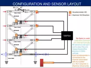
This document outlines the complete configuration and sensor layout for accelerometer testing, detailing the setup for measuring both in-plane and out-of-plane motions. Each sensor is calibrated with manually entered constants, ensuring precision in data acquisition. The system connects each accelerometer to its designated channel, with the hammer impact registered on Channel 8. Comprehensive details for in-plane and out-of-plane motion sensors are included, ensuring thorough documentation and guidelines for accurate measurement and testing procedures.

CONFIGURATION AND SENSOR LAYOUT
E N D
Presentation Transcript
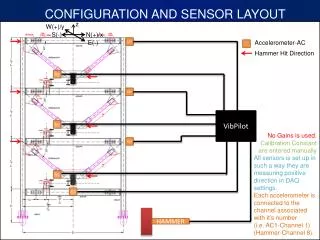
CONFIGURATION AND SENSOR LAYOUT z W(+)/y S(-) N(+)/x E(-) AC7 Hammer Hit Direction AC4 Accelerometer-AC AC6 VibPilot AC3 No Gains is used. Calibration Constant are entered manually All sensors is set up in such a way they are measuring positive direction in DAQ settings. Each accelerometer is connected to the channel associated with it’s number (i.e. AC1-Channel 1) (Hammer-Channel 8). AC5 AC2 AC1 HAMMER
DETAIL 1 DETAIL 3 DETAIL 1 DETAIL 3 DETAIL 1 DETAIL 3 DETAIL 2