2S Module Workshop, 30 Jan 2012 Module positioning and cooling contacts
160 likes | 353 Vues
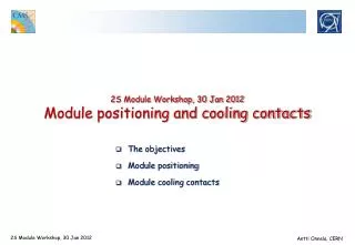
2S Module Workshop, 30 Jan 2012 Module positioning and cooling contacts. The objectives Module positioning Module cooling contacts. The objectives. Module positioning: Sufficiently precise initial geometry (< 1mm overall) to ensure module overlaps.

2S Module Workshop, 30 Jan 2012 Module positioning and cooling contacts
E N D
Presentation Transcript
2S Module Workshop, 30 Jan 2012Module positioning and cooling contacts • The objectives • Module positioning • Module cooling contacts Antti Onnela, CERN
The objectives • Module positioning: • Sufficiently precise initial geometry (< 1mm overall) to ensure module overlaps. • High stability (<< 0.1 mm) to minimize calibration needs during operation. • Cooling contacts between module and cooling pipe: • Silicon T max: -20 ºC, or preferably -25 ºC. • ΔT (silicon sensor – coolant) must be ≤ 10 ºC • To avoid need for very cold coolant.Though, we face a major problem here as the current pipe insulation is designed for -25 ºC and tested to -20 ºC .But, the coolant would need to be -30ºC or lower ! • The available ΔT of 10 ºC splits roughly into • ΔT (within module) < 7 ºC • ΔT (module cooling contact – module support piece – pipe wall) < 2 ºC. • ΔT (pipe wall – fluid) < 1 ºC, which seems achievable with 2-phase CO2. • Develop and qualify tracker-wide common solutions, keeping in mind different module types (2S, PS, Stereo, Vertical 3D) + Barrel and End-cap geometries. ΔT: 5-7 ºC Antti Onnela, CERN
Module positioning • In the present TK there is no common module positioning method • So, we have now a wider experience... Antti Onnela, CERN
Module positioning: TIB Inputs from A. Basti / INFN Pisa Inserts with clearance Precision insert Slot insert Antti Onnela, CERN
Module positioning: TEC Inputs from M. Wlochal / Aachen Antti Onnela, CERN
Module positioning: TOB Antti Onnela, CERN
And the net result with TK precision? Already after first cosmic runs the residuals with Track Based Alignment are at ~50um rms, and improve within 2008 to ~30um. Much better than what the mechanics can (reasonably) do! Antti Onnela, CERN
Module positioning • Sufficient precision can be reached with the TIB & TEC methods • Smaller and lighter than the TOB method • Maybe a sufficient precision can be reached even without positioning pins?! • Precision screw + hole / slot ? • Counter sunk screw + 2 holes or 1 hole and 1 slot ? • Use module edge as guide reference ? • Are inserts needed on the module? • Captive screws (permanently with module) could be excellent to have. • Not fully obvious, due small dimensions Tasks for 2012-2013: • Analyse the present TK results and set precision requirements for the upgrade TK. • Impacts the mechanics design from modules up to complete TK, as well as what needs to be done in terms of pre-alignment and measurements. • Produce test assemblies and measure their mechanical quality (precision, strength, ...). • Need sample materials/components for these tests ! Antti Onnela, CERN
Module cooling contacts • Different variants of module cooling contacts were applied in the present TK • So, we have now a wider experience... Antti Onnela, CERN
Module cooling: Present TK Support Antti Onnela, CERN
Module cooling • Uncertainties in calculation inputs (composites, glues, joints) measurements are necessary, though not fully obvious either (e.g. inputting of power load, availability of correct materials/components) • For the present tracker calculations and tests done mostly in 2000-2002 Antti Onnela, CERN
Module cooling currently (TOB) • Coolant temperature: 5 - 6 ºC. • Module power loads: • FE-power ~ 0.45 W / APV • Silicon self-heating ~ 0.014W / module @ 5 fb-1,0.4W / module expected @ 500 fb-1 (10y LHC) • Silicon mean temp: 13 – 14 ºC • ΔT (silicon - coolant) = 7 – 9 ºC • Will grow to ~ 10 ºC due self-heating increase DS modules P = 3.6W SS6 modules P = 2.7 W SS4 modules P = 1.8 W Cooling segment #44TOB 1.3.1 (132 modules) off Plots by Christian Barth Antti Onnela, CERN
Modulecoolingcontacts • Estimated power load in a 2S module: ~3.5 W (TOB: 1.8 – 4.4 W) • Following calculations (A. Mussgiller) and present TK experience ΔT (silicon – coolant) of 10 ºC seems reachable, but is not automatic! • 10 ºC easily ‘lost’ already within the module. • Good quality dry cooling contact can be sufficient • No need for thermal pastes. Avoid them, they are ‘dirty’ • But requires good planarity of the module and support contacts (no gaps, minimal stresses) • Even a small contact area is enough with these low powers, if the contact is good. Tasks for 2012-2013: • Study the support/cooling contacts in the modules • Is aluminium the choice? Any other candidates? • Study the module support/cooling blocks. • Is aluminium the choice? Any other candidates? • Geometry and dimensions. Connection to cooling pipe. • Qualification of assembly glues and methods, for all mechanical/thermal contacts • Produce test assemblies and measure their thermo-mechanical performance. • Need sample materials/components for these tests ! Antti Onnela, CERN
Thank you for your attention. Antti Onnela, CERN
Spare slides Antti Onnela, CERN
2S module, Jan 2012 version 3D models by A. Conde Garcia / CERN Antti Onnela, CERN