ICRI Advanced Gateway Operations Workshop
Join us for Module Two of the Advanced Gateway Operations Workshop, focusing on the Incident Commander’s Radio Interface (ICRI). Learn about setup, configuration, creating/breaking patches, and more. No extensive training required.

ICRI Advanced Gateway Operations Workshop
E N D
Presentation Transcript
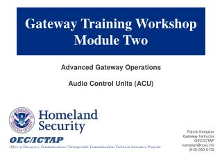
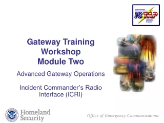
Gateway Training Workshop Module Two Advanced Gateway Operations Incident Commander’s Radio Interface (ICRI)
Advanced Gateway Operations Overview • Requirement & Capabilities • Setup & Configuration • Creating & Breaking Patches
Requirements & Capabilities • Equipment is patented by Communications - Applied Technology (C-AT) and there are various configurations ranging from 2 radios w/1 talkgroup to 10 radios w/4 talkgroups we will concentrate on the 5 radio, 2 talkgroups option • 5 radio I/O, 1 telephone I/O, handset/headset I/O, 2 talkgroups • Small (10” x 3” x 7”), rugged package/ circuitry • Portable (3.5 lbs) • Rapidly deployable (typically under 5 min.) • Minimal “operator” training required • Alternate power sources: 115-220V AC 50/60 Hertz, vehicle-supplied 12 volts DC, 8 AA Batteries
Requirements & Capabilities Power Options AC Adaptor Car battery 8 AA
A – DC Input Jack B – ON/OFF Switch C – OK/ Low Voltage LED D – OK/ Low Voltage LED E – Radio Interface Jacks (1 thru 5) Requirements & Capabilities Physical Layout F – Telephone Interface Jack G – Handset Interface Jack H – Handset Volume Control I – Voice Activated Circuit (VOX) LED Indicators J – Talk Group Switches
Setup & ConfigurationICRI with Attachments(Not to scale) 1. Ports are not radio specific (mobiles or portables) 2. User instructions on top cover 3. Interconnect cable technical notes on bottom cover
Setup & Configuration Prior to Activation Some pre-planning is necessary to ready the ICRI for use. The following should be accounted for before placing the ICRI on-line: • Predetermine what the power source will be for the ICRI and verify that the cable or battery pack is available • Predetermine what brand and model of radios will be connected to the ICRI and that an “interconnect” cable for each radio is available
Setup & Configuration Prior to Activation (Continued) • Advise agencies that they will need to supply a “spare” radio, for the radio interoperability, that the radio supplied must be known to operate properly and have at least one spare fully charged battery • Separate the interface radios • Ensure a clear field of view • Only connect agencies that need to interoperate • Coordinate gateway usage • Memorandums of Agreement (daily operations) • Communications Leader (COML) (per incident) • Interfacing non-standard radios, the radio’s owning organization should provide: • Interface cables • Spare batteries and/or chargers • Radio configuration/channel list
Setup & ConfigurationICRI Operation • After connecting a power source to the ICRI, turn it on so that power up and input voltage can be verified • When using a DC source voltage between 6.5 and 7.4 volts neither the OK nor the LOW voltage LEDs will light, but the ICRI will be function • Connect the radio interface cables to the ICRI (All five ICRI radio interface connections are electrically identical) • Connect the radio interface cables to the radios • Be sure the radios are on the channels assigned to the interoperability function • Turn on the radio
Creating & Breaking Patches ICRI • Select the talk-group the radio will be assigned to and place the switch above the associated port in the designated position NOTE: The center position of the switch places any item connected with the associated port into a “NO CONNECTION” conduction without physically disconnecting the device from the ICRI. • If used, connect the telephone and handset NOTE: For initial setup and troubleshooting purposes, C-AT recommends the use of the local handset or headset • Select the talk-group the telephone and/or handset will be associated with. • Turn on the telephone.
Questions ????