Download
1 / 48
530 likes | 863 Vues
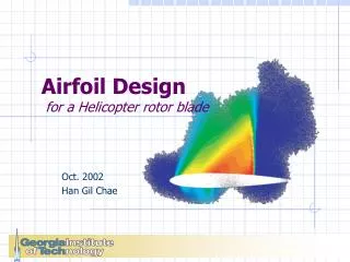
Helicopter Blade Lag Damping Using Embedded Inertial Dampers. Dr. Edward C. Smith Professor of Aerospace Engineering ecs5@psu.edu. Jason S. Petrie MS jpetrie@psu.edu. 2004 National Rotorcraft Technology Center Review May 3, 2005. Dr. George A. Lesieutre Professor of Aerospace Engineering

E N D
Helicopter Blade Lag Damping Using Embedded Inertial Dampers Dr. Edward C. Smith Professor of Aerospace Engineering ecs5@psu.edu Jason S. Petrie MS jpetrie@psu.edu 2004 National Rotorcraft Technology Center Review May 3, 2005 Dr. George A. Lesieutre Professor of Aerospace Engineering g-lesieutre@psu.edu
Presentation Outline • Background • Embedded Damper Concept • Objectives • Technical Approach • Accomplishments • Embedded Fluidlastic Damper Design • Experiment Hardware and Resuts • Conclusions
Aeromechanical Instabilities Major design considerations in the development of both Articulated and Hingeless Rotor Systems are Aeromechanical Instabilities (Ground Resonance and Air Resonance) An effective method to avoid these instabilities is the addition of Blade Lag Damping Lag Damper
State-of-the-Art Lag Dampers • Extremely High Maintenance • Many Critical Flight Conditions / Loads • Limited Life / High Cost of Replacement • Stroke Limits for Elastomeric Dampers • No Breakthrough Advances in Passive Rotor Blade Lag Damper Technology in the Last 20 Years
Embedded Inertial Dampers Simplified Hub Design Fewer Parts Less Constraints Chordwise Motion of the Mass Out of Phase with Rotor Blade Lag Motion Large Moment Arm Blade Cavity Mass Ma Elastomeric Spring Restoring Inertial Moment about the Lag Hinge Embedded Damper System Hebert, Lesieutre & Zapfe (1996 – 1998)
Embedded Inertial Dampers Viscous Root End Dampers Embedded Dampers
Embedded Dampers vs Root End Dampers Root End Damper Embedded Inertial Damper Difficulties with the Geometry of the Blade or Hub Yes (Especially with Bearingless Rotors) Yes (Small Blade Cavity) Moderate - Large Amount of Lag Damping Small - Moderate Possibly Reduce MLag (Stiff In-Plane?) Hub Loads Increases MLag Small Increase (Utilized Leading Edge Mass) Rotor Weight Moderate Increase Does Not Affect Hub Complexity of Rotor Hub Increases Does Not Affect Hub Rotor Hub Drag Increases Small Size Moderate to Large High Centrifugal Force Loading Yes No
Embedded Devices Embedded mechanical devices have been successfully integrated into full scale rotor blades. An embedded inertial damper will be subject to similar loads and geometric constraints as existing embedded devices. Reference: DARPA - Smart Rotor Program - 2004
Objectives Initial research shows that embedded inertial dampers may be promising for lag damping of rotor blades. In addition, embedded inertial dampers may utilize part of the leading edge weight of the blade and simplify the rotor hub considerably. Current Research Objectives: • Theoretical and experimental investigation of the feasibility of blade lag damping using embedded inertial dampers • Develop a physical understanding of blade lag damping with embedded inertial dampers (modal properties, stability, and response) • Establish design guidelines for rotor blade lag damping with embedded inertial dampers
Technical Approach • Theoretical Investigation of Blade Lag Damping Using Embedded Inertial Dampers • Develop Aeromechanical Stability Analysis for the Rotor-Fuselage-Damper System • Aeroelastic and Aeromechanical Stability Analysis of Rotor System with Embedded Damper • Parametric Study • Analysis Validation and Experimental Investigation of Blade Lag Damping Using Embedded Inertial Dampers • Isolated Blade Lag Damping • Aeromechanical Stability of Rotor System • Embedded Inertial Damper Device Design and Test
2004 RCOE Review • External Interactions • Lord Corporation • US Army • Sikorsky • Bell Helicopter
2001 - 2002 Accomplishments • Isolated Blade Lag Damping Experiment • Validated the Analytical Model and Concept • Revealed the Excessive Static Displacement of the Damper Mass • Identified the Technical Barriers • Developed an Understanding of the Design Issues Related to Embedded Chordwise Inertial Dampers • Modified Design Analysis to Capture Realistic Physics • Non-Linear Effects of the Static Lag Angle on Damper Response • Investigated Additional Conceptual Design Parameters • Angular and Radial Damper Response • Conducted an Initial Investigation of Blade Lag Damping Using Embedded Fluid Elastic Dampers • Developed a pure lag blade-embedded damper model • Conducted a parametric study
2003 Accomplishments • Conducted Initial Simulation of Rotor Blade Loads and Hub Vibration in Forward Flight • Refined Fluid Elastic Damper Model to Include All Necessary Fluid Motion Dynamics and Attributes • Conducted a Study of Blade Lag Damping Using Embedded Fluid Elastic Dampers • Conducted a parametric study to determine the effects of the fluid elastic element on rotor blade lag damping and the damper response • Compared the use of fluid elastic inertial dampers with elastomeric dampers previously investigated • Conducted feasibility study of embedded fluid elastic inertial dampers • Completed Initial Design of Fluid Elastic Damper with the Lord Corporation for Full Scale and Model Rotors
2004-05 Accomplishments Development of a New test facility to evaluate Lag Damper Technologies Completed Detailed Design of Fluid Elastic Damper with the Lord Corporation for Full Scale and Model Rotors Fabrication of Second Generation (Fluid Elastic) Embedded Inertial Damper Benchtop and initial rotor testing completed Published AIAA and AHS Conference Papers, MS Thesis, and AIAA Journal of Aircraft paper
Presentation Outline • Background • Embedded Fluidlastic Damper Design • Experiment Hardware and Resuts • Conclusions
ma ka* ao y a CG Elastomeric Damper Design Damper Equation of Motion: Damper Response:
Elastomeric Damper Design Issues • The static displacement of the embedded inertial damper may be excessive • A low damper tuning frequency is required to produce a suitable damping band for aeromechanical stability of system • An ideal embedded chordwise inertial damper for helicopter blade lag damping would have both a high static stiffness and a low dynamic stiffness
Conceptual Device Fluid Chamber Elastomer Inner Cylinder Damper Amplitude Outer Cylinder Mass Tuning Port Fluid Elastic Damper • High Static Stiffness • Low Dynamic Stiffness • As a result of blade lag motion, the damper mass oscillates in the lag direction and the fluid in the tuning port is pumped through the inner chamber. • Fluid motion creates a force which reduces the effective stiffness of the damper. The fluid force increases as the frequency of the system increases. • References: • Halwes (Bell Helicopter) 1980 • McGuire (Lord Corp.) 1994 • Kang (PSU) 2001
Fluid Elastic Damper Model Mass-Spring Equivalent of a Fluid-Elastomer Damper ap at = (G-1)ap mp at apo ka* mt ato b a Reference: Halwes (Bell Helicopter) 1980 mp = Damper Primary Mass mt = Tuning Mass = Fluid Mass = ALρ A = Tuning Port Cross Sectional Area L = Length of Tuning Port ρ = Density of Fluid G = b/a = Outer Cylinder-Tuning Port Area Ratio Parameters:
Mass Fluid Elastic Damper Design Fluid Mass Tuning Frequency Stiffness Tuning Port Area Ratio Step 1 • Establish an appropriate tuning frequency in order to maintain the aeromechanical stability of the rotor system
Mass Fluid Elastic Damper Design Fluid Mass Tuning Frequency Stiffness Tuning Port Area Ratio Step 2 • Establish the amount of mass that can be used within the blade cavity for the damper device • Embedded inertial dampers are intended to utilize part of the leading edge mass or part the tip mass of a rotor blade
Mass Fluid Elastic Damper Design Fluid Mass Tuning Frequency Stiffness Tuning Port Area Ratio Step 3 • Set the stiffness of the elastomer such that the device will be able to resist the centrifugal force at rotor speeds that correspond to the tuning frequency of the device
Mass Fluid Elastic Damper Design Fluid Mass Tuning Frequency Stiffness Tuning Port Area Ratio Step 4 • The fluid mass and the tuning port area ratio are then determined based on the equation for the elastomer stiffness
Mass Fluid Elastic Damper Design Fluid Mass Tuning Frequency Stiffness Tuning Port Area Ratio • The fluid mass and the tuning port area ratio will affect the overall size of the embedded fluid elastic damper The device must be able to fit within the blade
LORD CORPORATION Fluid Elastic Damper Design Conceptual Device Practical Device
Elastomer Element Outer Cylinder Helical Tuning Port Inner Cylinder Fluid Elastic Embedded Damper Spar (10 lbs) Hub Damper (1 lb)
Lord Corp. Helical Tuning Port Enables very high Tuning port ratios (G = 50+) Suited for compact embedded designs Elastomeric Element: The average stiffness was 2058 lbs/in at +- .010" and 5 Hz. Loss factor = .042
Benchtop Damper Test - Clear tuning frequency at 7.5 Hz - This shows fluid amplification effect
Fluid Elastic Damper Experiment Phase #1 – Spin Test Phase #2 – Bench Top Test Full Scale Embedded Fluid Elastic Inertial Damper for Commercial Rotor Blade System Scale Model Embedded Fluid Elastic Inertial Damper for New PSU Lag Test Stand Measure Blade Lag Damping and Frequency Measure Static and Dynamic Stiffness of Device • Examine the Stiffness Characteristics of the Damper • Validate Analytical Model and Damper Design
Fluid Elastic Damper Experiment Blade Flexure Actuator Hub Rotor Slip Ring Support Structure Hydraulic Motor
Fluid Elastic Damper Experiment • Steel Flexures • Dictates Lag Frequency • Interchangeable • Adds Strength
Fluid Elastic Damper Experiment • Embedded Actuator • Excites Blade • Tunable • Adds Versatility
Fluid Elastic Design - Full Scale • Simulated Annealing Algorithm (derived from RCOE Mount Task) • “Comanche-’like” rotor properties (R = 20ft, Lag freq = 3.5 Hz) • 3% critical damping • Absorber tuning Freq = 4.9 Hz (based on 220 RPM crossing) • Damper limit of 10% blade mass, 1%chord dynamic stroke
Fluid Elastic Design - Full Scale • Target Damping Level Achieved within realistic constraints • Other variations possible based on modified objectives
Fluid Elastic Damper- Model Test Predictions • Prototype damper fabricated at Lord Corp
Fluid Elastic Damper- Model Test Predictions • Very low static displacement (no instability) • Proper tuning freq and low dynamic stroke
Presentation Outline • Background • Rotor Loads and Vibration Simulation • Embedded Damper Design • Elastomeric Damper vs. Fluid Elastic Damper • Fluid Elastic Damper Design and Experiment • Conclusions
Conclusions • An embedded fluid elastic inertial damper is capable of producing rotor blade lag damping within a desirable frequency band for aeromechanical stability of the system. • The static stiffness of a fluid elastic inertial damper is large enough to maintain a reasonable static amplitude. • aStatic / ao< 5% of the Chord • Static Instability Problem Resolved!
Conclusions • A new lag damping test rig was successfully designed and brought online • Detailed Design and Fabrication of a Compact Second Generation (Fluid Elastic) Embedded Inertial Damper was completed • Benchtop testing of the new device confirmed the dynamic characteristics predicted by design analysis
Publications and Presentations • AIAA SDM Conference (April 2002) • Lord Corporporation (May 2002) • Sikorsky (June 2002) • ARO Aeroelasticity Workshop (November 2003) • Lord Corporation (February 2004) • AIAA Journal of Aircraft Paper (Accepted March 2004) • AIAA SDM Conference (April 2004) • Jason Petrie MS Thesis (August 2004) • Boeing, Mesa (January 2005) • Lord Corporation R&D Center (March 2005) • AHS Forum (June 2005)
2005 Plans • Complete spin testing of embedded damper devices • Complete additional analysis of vibratory hub loads and chordwise blade loads in forward flight (Dr. Zhang) • Explore opportunities for industry team for further development of full scale prototype (including designs effective for both articulated and BMR)
Schedule and Milestones 2005 2004 2001 2002 2003 Tasks STAGE ONE Fundamental Study System Modeling Stability Analysis Blade Lag Damping Test STAGE TWO Model Refined Parametric Study Concept Design of Absorber Fluid Elastic Damper Test STAGE THREE Design of Absorber Rotor Loads & Vibration Report, Guideline of Design Completed Short Term Long Term
Helicopter Blade Lag Damping Using Embedded Fluid Elastic Inertial Dampers Questions? This project is co-funded by the Lord Corporation (Project Technical Monitors: John Heilman, Denny McGuire)
ao y a Previous Accomplishments • Basic Study of Blade Lag Damping Using Embedded Inertial Dampers (Kang, Smith & Lesieutre 1999 – 2001) Rigid Blade/Embedded Damper Model Parametric Study • Developed an analytical model of a rotor system with an embedded damper • Demonstrated that an elastomeric device could produce blade lag damping
Previous Accomplishments • Aeromechanical Stability Analysis for Rotor – Fuselage – Embedded Inertial Damper(Kang, Smith & Lesieutre 2001 - 2002) Damper Mass: 0.1 (Ma/Mb) Location: 1.0R Tuned Frequency: 13.95 Hz (0.84W0) Loss Factor: 0.5 Consider a Hingeless Rotor System with Embedded Inertial Damper (AFDD Rotor) • Indicated that embedded chordwise dampers had the potential to maintain the aeromechanical stability of helicopters
Blade Properties Number of Blades 2 Radius, in 19.5 Chord, in 0.5 Rotation Speed, RPM 0-300 Nonrotating Lag Freq., Hz 4, 6.5 Lag Damping, % Critical 0.3 Damper Properties Mass (lbm) Frequency Loss Factor 1 0.0355 8.9 Hz 0.38 2 0.042 7.6 Hz 0.39 3 0.042 6.3 Hz 0.42 4 0.0485 5.5 Hz 0.41 Previous Accomplishments • Isolated Blade Lag Damping Tests (Kang, Smith & Lesieutre 2001 – 2002)
Previous Accomplishments RESULTS