Assembler
Dive into the abstract design of software and computer architecture with chapters on assembly, machine language, and operating system interfaces. Explore the hierarchy of thought in electrical engineering and logic gates. Learn to create assemblers and compilers.

Assembler
E N D
Presentation Transcript
Assembler Building a Modern Computer From First Principles www.nand2tetris.org
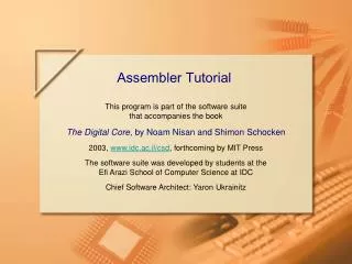
Abstract design Software Human abstract interface Thought hierarchy Chapters 9, 12 H.L. Language & abstract interface Operating Sys. VM Translator Virtual abstract interface Compiler Machine Chapters 7 - 8 Assembly Chapters 10 - 11 Language Assembler Chapter 6 abstract interface Computer Architecture Machine abstract interface Language Chapters 4 - 5 Gate Logic Hardware abstract interface Platform Chapters 1 - 3 Electrical Engineering Chips & Hardware Physics Logic Gates hierarchy Where we are at:
Why care about assemblers? Because … • Assemblers employ nifty programming tricks • Assemblers are the first rung up the software hierarchy ladder • An assembler is a translator of a simple language • Writing an assembler = low-impact practice for writing compilers.
Source code (example) Target code // Computes 1+...+RAM[0] // And stored the sum in RAM[1] @i M=1 // i = 1 @sum M=0 // sum = 0 (LOOP) @i // if i>RAM[0] goto WRITE D=M @R0 D=D-M @WRITE D;JGT ... // Etc. 0000000000010000 1110111111001000 0000000000010001 1110101010001000 0000000000010000 1111110000010000 0000000000000000 1111010011010000 0000000000010010 1110001100000001 0000000000010000 1111110000010000 0000000000010001 ... assemble Assembly example For now, ignore all details! execute The program translation challenge • Extract the program’s semantics from the source program, using the syntax rules of the source language • Re-express the program’s semantics in the target language,using the syntax rules of the target language Assembler = simple translator • Translates each assembly command into one or more binary machine instructions • Handles symbols (e.g. i, sum, LOOP, …).
CPU emulator screen shotafter running this program user supplied input program generated output Revisiting Hack low-level programming: an example Assembly program (sum.asm) // Computes 1+...+RAM[0] // And stores the sum in RAM[1]. @i M=1 // i = 1 @sum M=0 // sum = 0 (LOOP) @i // if i>RAM[0] goto WRITE D=M @0 D=D-M @WRITE D;JGT @i // sum += i D=M @sum M=D+M @i // i++ M=M+1 @LOOP // goto LOOP 0;JMP (WRITE) @sum D=M @1 M=D // RAM[1] = the sum (END) @END 0;JMP The CPU emulator allows loading and executing symbolic Hack code. It resolves all the symbolic symbols to memory locations, and executes the code.
The assembler’s view of an assembly program Assembly program // Computes 1+...+RAM[0] // And stores the sum in RAM[1]. @i M=1 // i = 1 @sum M=0 // sum = 0 (LOOP) @i // if i>RAM[0] goto WRITE D=M @0 D=D-M @WRITE D;JGT @i // sum += i D=M @sum M=D+M @i // i++ M=M+1 @LOOP // goto LOOP 0;JMP (WRITE) @sum D=M @1 M=D // RAM[1] = the sum (END) @END 0;JMP Assembly program = a stream of text lines, each being one of the following: • A-instruction • C-instruction • Symbol declaration: (SYMBOL) • Comment or white space:// comment The challenge: Translate the program into a sequence of 16-bit instructions that can be executed by the target hardware platform.
Translating / assembling A-instructions Translation to binary: • If value is a non-negative decimal number, simple • If value is a symbol, later.
Translating / assembling C-instructions Translation to binary: simple!
Assembly program // Computes 1+...+RAM[0] // And stores the sum in RAM[1]. @i M=1 // i = 1 @sum M=0 // sum = 0 (LOOP) @i // if i>RAM[0] goto WRITE D=M @0 D=D-M @WRITE D;JGT @i // sum += i D=M @sum M=D+M @i // i++ M=M+1 @LOOP // goto LOOP 0;JMP (WRITE) @sum D=M @1 M=D // RAM[1] = the sum (END) @END 0;JMP The overall assembly logic For each (real) command • Parse the command,i.e. break it into its underlying fields • A-instruction: replace the symbolic reference (if any) with the corresponding memory address,which is a number • (how to do it, later) • C-instruction: for each field in the instruction, generate the corresponding binary code • Assemble the translated binary codes into a complete 16-bit machine instruction • Write the 16-bit instruction to the output file.
Assembly programs typically have many symbols: Labels that mark destinations of goto commands Labels that mark special memory locations Variables These symbols fall into two categories: User–defined symbols (created by programmers) Pre-defined symbols (used by the Hack platform). Typical symbolic Hackassembly code: @R0 D=M @END D;JLE @counter M=D @SCREEN D=A @x M=D (LOOP) @x A=M M=-1 @x D=M @32 D=D+A @x M=D @counter MD=M-1 @LOOP D;JGT (END) @END 0;JMP Handling symbols (aka symbol resolution)
Label symbols: Used to label destinations of goto commands. Declared by the pseudo-command (XXX). This directive defines the symbol XXX to refer to the instruction memory location holding the next command in the program Variable symbols: Any user-defined symbol xxx appearing in an assembly program that is not defined elsewhere using the (xxx)directive is treated as a variable, and is automatically assigned a unique RAM address, starting at RAM address 16 (why start at 16? Later.) By convention, Hack programmers use lower-case and upper-case to represent variable and label names, respectively Typical symbolic Hackassembly code: @R0 D=M @END D;JLE @counter M=D @SCREEN D=A @x M=D (LOOP) @x A=M M=-1 @x D=M @32 D=D+A @x M=D @counter MD=M-1 @LOOP D;JGT (END) @END 0;JMP Handling symbols: user-defined symbols Q: Who does all the “automatic” assignments of symbolsto RAM addresses? A: As part of the program translation process, the assembler resolves all the symbols into RAM addresses.
Typical symbolic Hackassembly code: @R0 D=M @END D;JLE @counter M=D @SCREEN D=A @x M=D (LOOP) @x A=M M=-1 @x D=M @32 D=D+A @x M=D @counter MD=M-1 @LOOP D;JGT (END) @END 0;JMP Handling symbols: pre-defined symbols Virtual registers:The symbols R0,…, R15 are automatically predefined to refer to RAM addresses 0,…,15 I/O pointers: The symbols SCREEN and KBD are automatically predefined to refer to RAM addresses 16384 and 24576, respectively (base addresses of the screen and keyboard memory maps) VM control pointers: the symbols SP, LCL, ARG, THIS, and THAT (that don’t appear in the code example on the right)are automatically predefined to refer to RAM addresses 0 to 4, respectively (The VM control pointers, which overlap R0,…, R4 will come to play in the virtual machine implementation, covered in the next lecture) Q: Who does all the “automatic” assignments of symbolsto RAM addresses? A: As part of the program translation process, the assembler resolves all the symbols into RAM addresses.
Source code (example) // Computes 1+...+RAM[0] // And stored the sum in RAM[1] @i M=1 // i = 1 @sum M=0 // sum = 0 (LOOP) @i // if i>RAM[0] goto WRITE D=M @R0 D=D-M @WRITE D;JGT @i // sum += i D=M @sum M=D+M @i // i++ M=M+1 @LOOP // goto LOOP 0;JMP (WRITE) @sum D=M @R1 M=D // RAM[1] = the sum (END) @END 0;JMP Handling symbols: symbol table Symbol table R0 0 R1 1 R2 2 ... ... R15 15 SCREEN 16384 KBD 24576 SP 0 LCL 1 ARG 2 THIS 3 THAT 4 WRITE 18 END 22 i 16 sum 17 This symbol table is generated by the assembler, and used to translate the symbolic code into binary code.
Handling symbols: constructing the symbol table Source code (example) Symbol table // Computes 1+...+RAM[0] // And stored the sum in RAM[1] @i M=1 // i = 1 @sum M=0 // sum = 0 (LOOP) @i // if i>RAM[0] goto WRITE D=M @R0 D=D-M @WRITE D;JGT @i // sum += i D=M @sum M=D+M @i // i++ M=M+1 @LOOP // goto LOOP 0;JMP (WRITE) @sum D=M @R1 M=D // RAM[1] = the sum (END) @END 0;JMP R0 0 R1 1 R2 2 ... R15 15 SCREEN 16384 KBD 24576 SP 0 LCL 1 ARG 2 THIS 3 THAT 4 WRITE 18 END 22 i 16 sum 17 Initialization: create an empty symbol table and populate it with all the pre-defined symbols First pass: go through the entire source code, and add all the user-defined label symbols to the symbol table (without generating any code) Second pass: go again through the source code, and use the symbol table to translate all the commands. In the process, handle all the user-defined variable symbols.
The assembly process (detailed) • Initialization: create the symbol table and initialize it with the pre-defined symbols • First pass: march through the source code without generating any code.For each label declaration (LABEL) that appears in the source code,add the pair <LABEL,n > to the symbol table • Second pass: march again through the source code, and process each line: • If the line is a C-instruction, simple • If the line is @xxx where xxx is a number, simple • If the line is @xxx and xxx is a symbol, look it up in the symbol table and proceed as follows: • If the symbol is found, replace it with its numeric value and complete the command’s translation • If the symbol is not found, then it must represent a new variable:add the pair <xxx,n > to the symbol table, where n is the next available RAM address, and complete the command’s translation. • (Platform design decision: the allocated RAM addresses are running,starting at address 16).
The result ... Source code (example) Target code // Computes 1+...+RAM[0] // And stored the sum in RAM[1] @i M=1 // i = 1 @sum M=0 // sum = 0 (LOOP) @i // if i>RAM[0] goto WRITE D=M @R0 D=D-M @WRITE D;JGT @i // sum += i D=M @sum M=D+M @i // i++ M=M+1 @LOOP // goto LOOP 0;JMP (WRITE) @sum D=M @R1 M=D // RAM[1] = the sum (END) @END 0;JMP 0000000000010000 1110111111001000 0000000000010001 1110101010001000 0000000000010000 1111110000010000 0000000000000000 1111010011010000 0000000000010010 1110001100000001 0000000000010000 1111110000010000 0000000000010001 1111000010001000 0000000000010000 1111110111001000 0000000000000100 1110101010000111 0000000000010001 1111110000010000 0000000000000001 1110001100001000 0000000000010110 1110101010000111 assemble Note that comment lines and pseudo-commands (label declarations) generate no code.
Proposed assembler implementation An assembler program can be written in any high-level language. We propose a language-independent design, as follows. Software modules: • Parser: Unpacks each command into its underlying fields • Code: Translates each field into its corresponding binary value, and assembles the resulting values • SymbolTable: Manages the symbol table • Main: Initializes I/O files and drives the show. Proposed implementation stages • Stage I: Build a basic assembler for programs with no symbols • Stage II: Extend the basic assembler with symbol handling capabilities.
Parser (a software module in the assembler program) / continued
Perspective • Simple machine language, simple assembler • Most assemblers are not stand-alone, but rather encapsulated in a translator of a higher order • C programmers that understand the code generated by a C compiler can improve their code considerably • C programming (e.g. for real-time systems) may involve re-writing critical segments in assembly, for optimization • Writing an assembler is an excellent practice for writing more challenging translators, e.g. a VM Translator and a compiler, as we will do in the next lectures.