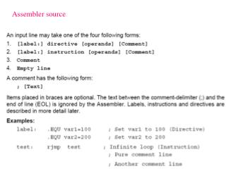
AVR Assembler
AVR Assembler. Branches Subroutines and Memory usage. Outline. Memory on the AVR processor Addressing modes for accessing memory Program Flow: Subroutines and the stack Memory Test Program Program Design The LED display program. Memory in the AVR.

AVR Assembler
E N D
Presentation Transcript
AVR Assembler Branches Subroutines and Memory usage M. Neil - Microprocessor Course
Outline Memory on the AVR processor Addressing modes for accessing memory Program Flow: Subroutines and the stack Memory Test Program Program Design The LED display program M. Neil - Microprocessor Course
Memory in the AVR There are Several different types of memory on the AVR which you can use/access Flash Program Memory Data SRAM (internal and external) Registers EEPROM M. Neil - Microprocessor Course
Program Memory • Organized as 64K 16bit words • Addressed $0000-$FFFF • 128 Kilo-Bytes of memory • This is where the program which is executing is stored • The Program Counter (PC) holds the address in program memory of the current instruction • Data can be stored in program memory • The data stored in program memory needs to be copied into data memory before it can be used – there is a special instruction (LPM) for doing this M. Neil - Microprocessor Course
Data Memory • There is some internal memory (SRAM) on the Atmega128 which can be used for storing data (and also the Stack) • Internal SRAM memory is 4K X 8 bits (4 Kilo-Bytes $0100-$10FF) • The registers and I/O ports occupy the lower part of this memory (Addresses $0000-$00FF) • There is also the possibility of external memory being installed • Not on our boards • Can add if your project needs M. Neil - Microprocessor Course
Registers The registers actually occupy the lowest 32 bytes of internal SRAM. Most registers can be used generally for 8 bit operations R16-R31 can be used with the ldi instruction R26-r31 can also be used as the X/Y/Z address registers M. Neil - Microprocessor Course
Accessing memory – Addressing modes neg r20 R20 $00-r20 add r20,r24 R20 r20+r24 M. Neil - Microprocessor Course
Addressing Input/Output memory in r20,PIND R20 PIND out PORTB,r16 • PORTB r16 • There are 6 I/O ports • PORTA-PORTG • Each has • PINX • Input Port • DDRX • Data Direction Register • PORTX • Output Port M. Neil - Microprocessor Course
Working with SRAM Data .equmyVariable = $0208 lds r16, myVariable sbi r16, $22 stsmyVariable, r16 We can define addresses where we want to store variables, and move data in and out of the SRAM with the lds,stsinstructions M. Neil - Microprocessor Course
Using the X, Y, Z registers to address SRAM .equmyVariable = $0208 • ldi XL, low(myVariable) ;load XL(r26):XH(r27) with • ldi XH, high(myVariable) ;address of myVariable ld r16,X ;copy data from SRAM sbir16, $22 ;subtract 34 from the byte st X,r16 ;store result in SRAM • The registers r26-r31 are special and can be used to store an address (16 bits $0000-$FFFF) which points to the SRAM • r26:r27 is XL:XH • r28:r29 is YL:YH • r30:r31 is ZL:ZH • With these registers, any location in SRAM can be read from or written to • ld r16,Y • There are also pre/post increment/decrement modes to make it quicker to address arrays of data • ld r3,Z+ • ld r7,–X M. Neil - Microprocessor Course
Program Memory and LPM - a picture Using the Z register to point at program memory Program Memory We multiply the address by 2 to select which 16 bit word The Least Significant Bit (LSB) is then used to select which byte to read with the LPM instruction M. Neil - Microprocessor Course
Copying data from PM to SRAM .equmyArray=$0800 ; Address in SRAM ldiZH,high(myTable*2) ; Load the Zregister with the ldiZL,low(myTable*2) ; address of data in PM ldiXH,high(myArray) ; Load X register with the ldiXL,low(myArray) ; address in SRAM ldir16,22 ; there are 22 bytes to copy loop: lpm r17,Z+ ; moveone byte from PM to r17 st X+,r17 ; store in SRAM (and increment) dec r16 ; count down bytescopied brneloop ; keepgoinguntilfinished ret myTable: .db “Thisis just some data” Can use only the Z register to copy data from PM to a register. Auto increment modes make more compact code – Use the special lpm instruction M. Neil - Microprocessor Course
More details about Program memory ; **** RAMPZ SetupCode **** ldi r16,$00 ; 1 = ELPM acts on upper 64K out RAMPZ,r16 ; 0 = ELPM acts on lower 64K • The Z register is only 16 bits wide • Can address 64K Bytes • There are 128K Bytes of flash program memory • The LPM instruction addresses the lower 64K Bytes • The RAMPZ register allows access to the upper 64K Bytes with the ELPM instruction M. Neil - Microprocessor Course
Storing data in program memory • You can create initial values for data in your program code • These will be stored in the program memory • Accessed using the labels you define • See the examples below for the assembler directives needed to create data in the • You can copy them into SRAM (as we did on the previous page) or use them directly from the program memory • Access will be quicker from SRAM and values can be changed MyByteTable: .DB $00,$01,$02,$03,$04,$05,$06,$07;Table loading with 8 bytes MyWordTable: .DW $0908,$0B0A,$0D0C,$0F0E,$1110 ; Load 5 16-bit words in the table .DW $1514,$1617,$1918,$1B1A,$1D1C ; Next 5 16-bit words in the table MyStringTable: .DB “abcdefghijklmnopqrstuvwxyz” ; Line of ascii characters M. Neil - Microprocessor Course
Sometimes we need to work with numbers larger than 8 bits There are Word operations which can be used to perform 16 bit operations on the upper 4 register pairs (25:24,27:26,29:28, 31:30) adiw - add immediate to word sbiw – subtract immediate to word We can also use the carry bits for longer numbers – this requires some coding adc– add with carry sbc – subtract with carry longloop: ldiXH,high($DEAD) ;put large number ldiXL,low($DEAD) ;in X register loop: sbiw XH:XL,1 ;subtract 1 from X brne loop ;continue till 0 ret Using 16 Bit Counters M. Neil - Microprocessor Course
Program Flow, subroutines, local variables You will want to break your program up into small pieces or subroutines You will need to set up loops to repeat small pieces of program A special register called the stack pointer is used to call subroutines, and temporarily store registers when using subroutines The simulator can help you understand what is happening in your program as well M. Neil - Microprocessor Course
SRAM usage The on-board RAM must hold the Stack Pointer The Stack Pointer keeps track of where the program execution has been Allows temporary storage of registers SRAM also holds data variables Typical to have Stack grow downwards and data grow upwards Must avoid stack/data collisions! ; ***** Stack Pointer Setup Code ldi r16, $10; Stack Pointer Setup out SPH,r16 ; Stack Pointer High Byte ldi r16, $FF ; Stack Pointer Setup out SPL,r16 ; Stack Pointer Low Byte M. Neil - Microprocessor Course
rcallmysub • PC+1 stored on stack • PC is changed to mysub: • ret • PC is popped from the stack Subroutines:call,rcall,icall call to a small unit of code which does a given task Good Practice to push/pop any registers used in the subroutine push r24 – stores r24 register byte at the location in the Stack Pointer (SP) then decrements the SP pop r24 – loads r24 with the byte pointed to by SP then increments the SP Must call retat the end of the subroutine main: rcall wait ; call our subroutine rjmp main wait:push r24 ; preserve r24 ldi r24,$FF ; loop: dec r24 ; count down bytes brne loop ; keep going until finished pop r24 ; restore r24 ret M. Neil - Microprocessor Course
Functions: main: ldi r24,3 ; input parameter in r24 rcall mult10 ; call our subroutine out PORTB,r24 ; put the answer on the LED rjmp main mult10:push r25 ; preserve r25 push r26 ; preserve r26 ldi r25,$0A ; we will multiply by 10 ldi r26,$00 ; sum initialized to 0 loop: add r26,r24 ; add r24 to the sum dec r25 brne loop ; keep going until finished mov r24,r26 ; put sum in r24 pop r26 ; restore r26 pop r25 ; restore r25 ret ; return with answer in r24 Call to a small unit if code which does a given task Can depend on input parameters – passed to the function in registers or on the stack Good Practice to push/pop any registers used in the subroutine Must call ret at the end of the subroutine Result stored in a register M. Neil - Microprocessor Course
Stack Pointer – Examples, Call 22: 0e 94 7f 00 call 0xfe 26:97 01 movwr18, r14 ….. ; ; our subroutine ; fe: ef 92 push r14 ;do some things – and use r14 ; for whatever we want 100:7c 01 movw r14, r24 ; 13e: ef 90 pop r14 140: 08 95 ret M. Neil - Microprocessor Course
Stack Pointer – Examples, Call 22: 0e 94 7f 00 call 0xfe 26:97 01 movwr18, r14 ….. ; ; our subroutine ; fe: ef 92 push r14 ;do some things – and use r14 ; for whatever we want 100:7c 01 movw r14, r24 ; 13e: ef 90 pop r14 140: 08 95 ret M. Neil - Microprocessor Course
Stack Pointer – Examples, Call 22: 0e 94 7f 00 call 0xfe 26:97 01 movwr18, r14 ….. ; ; our subroutine ; fe: ef 92 push r14 ;do some things – and use r14 ; for whatever we want 100:7c 01 movw r14, r24 ; 13e: ef 90 pop r14 140: 08 95 ret M. Neil - Microprocessor Course
Stack Pointer – Examples, Call 22: 0e 94 7f 00 call 0xfe 26:97 01 movwr18, r14 ….. ; ; our subroutine ; fe: ef 92 push r14 ;do some things – and use r14 ; for whatever we want 100:7c 01 movw r14, r24 ; 13e: ef 90 pop r14 140: 08 95 ret M. Neil - Microprocessor Course
Stack Pointer – Examples, Call 22: 0e 94 7f 00 call 0xfe 26:97 01 movwr18, r14 ….. ; ; our subroutine ; fe: ef 92 push r14 ;do some things – and use r14 ; for whatever we want 100:7c 01 movw r14, r24 ; 13e: ef 90 pop r14 140: 08 95 ret M. Neil - Microprocessor Course
Stack Pointer – Examples, Call 22: 0e 94 7f 00 call 0xfe 26:97 01 movwr18, r14 ….. ; ; our subroutine ; fe: ef 92 push r14 ;do some things – and use r14 ; for whatever we want 100:7c 01 movw r14, r24 ; 13e: ef 90 pop r14 140: 08 95 ret M. Neil - Microprocessor Course
Stack Pointer – Examples, Call 22: 0e 94 7f 00 call 0xfe 26:97 01 movwr18, r14 ….. ; ; our subroutine ; fe: ef 92 push r14 ;do some things – and use r14 ; for whatever we want 100:7c 01 movw r14, r24 ; 13e: ef 90 pop r14 140: 08 95 ret M. Neil - Microprocessor Course
Exercises: • Exercise 1 : Last time you made a counter. Now use a subroutine to delay the speed of the counter. • Exercise 2 : You can delay further by cascadingdelay subroutines. • Exercise 3 :Memory Test Program: Write a program that writes (st) incrementing numbers to the SRAM. Read (ld) them back, compare with what you expect to see and if it is not correct send a pattern of lights to PORTB. • What happens if you start writing before address $0100 M. Neil - Microprocessor Course
LED sequence display • Write a program that puts the contents of a table into program memory and then reads the contents back sequentially, byte by byte, and outputs them to the LEDs on PORTB. • Chose the bytes so that they will make a pattern when they are displayed on the LEDs • Use delays to slow down the program so you can see the different patterns flashing as they light the LEDS on PORTB. • Allow the user to change the speed of flashing using the switches on PORTD • Allow the user to start/stop the pattern using switches on PORTD M. Neil - Microprocessor Course
Structured Programming • Design your programme into a main control segment, which calls sub-routines • marks will be given on the modularity of your code • Before starting to write code make a simple design diagram outlining the tasks which need to be done • Take 5-10 minutes, and show this to your demonstrator • Use a Top Down Modular Programming approach to design • Subroutines should perform specific tasks or repeated functions • Put lots of comments in your code M. Neil - Microprocessor Course
Top Down Modular Programming time complexity Calculator Initialise Get command Calculate Output Reset Prompt message Input Interpret command Select/run routine Format output Display Load values Input character Output character Output character Output character M. Neil - Microprocessor Course