SPL cryomodule specification: Preliminary summary
60 likes | 192 Vues
This document outlines preliminary specifications and discussion points for the SPL cryomodule, focusing on testing possibilities in a beamline, magnetic shielding, and active cooling requirements. Key aspects include establishing cooling targets (50K thermal shield), instrumentation needs, space allocation for cryogenic connections, and maintenance considerations. The need for precise temperature monitoring, heat load assessments, and the development of a magnetic field map in the SM18 bunker are highlighted. The document encourages collaboration and further discussions on redundancy, alignment monitoring, and RF coupler designs.

SPL cryomodule specification: Preliminary summary
E N D
Presentation Transcript
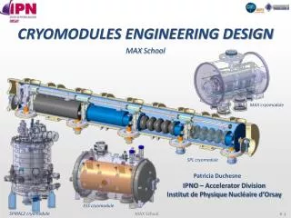
SPL cryomodule specification:Preliminary summary V.Parma, TE-MSC
issues • Keep possibility for testing cryomodule in a beam line. Where could it be tested? • Magnetic shielding • 1st shield cryo-perm: active cooling? What T? Dedicated circuit? Active solution of Spiral 2 cryomodule seems interesting • 2nd shield @ RT • “fast” cool down requirement (Q desease): 100 K/h as a goal though not a specif requirement yet (vertical tests will tell us) • No active cooling of inter-cavity bellows, but T measurement • HL measurements. • Pressure gauge measurement rather than T helium, but having T cavity measured is useful (cryo), but no need for precision (could be in insulation vacuum) • Flow-meter could be useful • T of thermal shield should be close to 50 K. This needs a dedictated line in SM18 or an artifact, to increase T to 50K. Dp is limited. To be checked with thermalshield geometry. • Make a specific table of T for the test bench in SM18 • Heat Loads table: discussed and confirmed • Clarify warm-up means (boir-off of helium, followed by vac.degradation?) • Space allocation in bunker for cryogenic connection activity • Connection to cryo distribution line:.Confirmed: • Welded solution for connection to the cryo distribution line • Flexibility on connection to allow tilt change (0-2%)
Other issues from CNRS • Magnetic shielding. Additional points: • Definition of the interfaces: • Tank and cavity support • Instrumentation • Making a magneticfieldmap of SM18 bunker. • Evaluatethe needs of maintenance actions on/in the cryomodule… (for design of windows) • Frequency • Type of maintenance • On the experimental site • In an intervention zone (= assembly zone) Yes, need access windows to access tuners (motor), HOM (there are 2), RF vac. Transitions ...frequency of intervention not discussed
Issues • Instrumentation. Quite an exhaustive list presented by system responsible: • Priority and Redundancy to be further discussed • Alignment budgets: cavity figures considered tight, but overall figures OK. Reconsider sharing? • Aligment monitoring (WPM or similar) is a must to confirm the new supporting concept • RF coupler “2-in1” concept. Suggested dedicated mock-up for testing the mechanics and of vacuum integrity (RF gasket). Yes!
Other issues • Cryogenic scheme. SPL slope-specific. • Cryogenic valves/filling scheme is redundant, yes, but wanted. Aim is to test and eventually simplify. • Dark current measurements
Thanks to all participants (especially speakers!) for the fruitful meeting