Pure Bending
4. Pure Bending. Pure Bending Other Loading Types Symmetric Member in Pure Bending Bending Deformations Strain Due to Bending Beam Section Properties Properties of American Standard Shapes Deformations in a Transverse Cross Section Sample Problem 4.2

Pure Bending
E N D
Presentation Transcript
4 Pure Bending
Pure Bending Other Loading Types Symmetric Member in Pure Bending Bending Deformations Strain Due to Bending Beam Section Properties Properties of American Standard Shapes Deformations in a Transverse Cross Section Sample Problem 4.2 Bending of Members Made of Several Materials Example 4.03 Reinforced Concrete Beams Sample Problem 4.4 Stress Concentrations Plastic Deformations Members Made of an Elastoplastic Material Example 4.03 Reinforced Concrete Beams Sample Problem 4.4 Stress Concentrations Plastic Deformations Members Made of an Elastoplastic Material Plastic Deformations of Members With a Single Plane of S... Residual Stresses Example 4.05, 4.06 Eccentric Axial Loading in a Plane of Symmetry Example 4.07 Sample Problem 4.8 Unsymmetric Bending Example 4.08 General Case of Eccentric Axial Loading Pure Bending
Pure Bending Pure Bending: Prismatic members subjected to equal and opposite couples acting in the same longitudinal plane
Eccentric Loading: Axial loading which does not pass through section centroid produces internal forces equivalent to an axial force and a couple • Transverse Loading: Concentrated or distributed transverse load produces internal forces equivalent to a shear force and a couple Other Loading Types • Principle of Superposition: The normal stress due to pure bending may be combined with the normal stress due to axial loading and shear stress due to shear loading to find the complete state of stress.
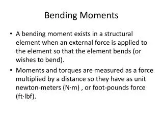
Internal forces in any cross section are equivalent to a couple. The moment of the couple is the section bending moment. • These requirements may be applied to the sums of the components and moments of the statically indeterminate elementary internal forces. Symmetric Member in Pure Bending • From statics, a couple M consists of two equal and opposite forces. • The sum of the components of the forces in any direction is zero. • The moment is the same about any axis perpendicular to the plane of the couple and zero about any axis contained in the plane.
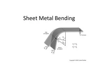
Beam with a plane of symmetry in pure bending: • member remains symmetric Bending Deformations • bends uniformly to form a circular arc • cross-sectional plane passes through arc centerand remains planar • length of top decreases and length of bottom increases • a neutral surface must exist that is parallel to the upper and lower surfaces and for which the length does not change • stresses and strains are negative (compressive) above the neutral plane and positive (tension) below it
Strain Due to Bending Consider a beam segment of length L. After deformation, the length of the neutral surface remains L. At other sections,
For static equilibrium, • For static equilibrium, First moment with respect to neutral plane is zero. Therefore, the neutral surface must pass through the section centroid. Stress Due to Bending • For a linearly elastic material,
The maximum normal stress due to bending, A beam section with a larger section modulus will have a lower maximum stress • Consider a rectangular beam cross section, Between two beams with the same cross sectional area, the beam with the greater depth will be more effective in resisting bending. • Structural steel beams are designed to have a large section modulus. Beam Section Properties
Deformation due to bending moment M is quantified by the curvature of the neutral surface • Although cross sectional planes remain planar when subjected to bending moments, in-plane deformations are nonzero, • Expansion above the neutral surface and contraction below it cause an in-plane curvature, Deformations in a Transverse Cross Section
SOLUTION: • Based on the cross section geometry, calculate the location of the section centroid and moment of inertia. • Apply the elastic flexural formula to find the maximum tensile and compressive stresses. A cast-iron machine part is acted upon by a 3 kN-m couple. Knowing E = 165 GPa and neglecting the effects of fillets, determine (a) the maximum tensile and compressive stresses, (b) the radius of curvature. • Calculate the curvature Sample Problem 4.2
Sample Problem 4.2 SOLUTION: Based on the cross section geometry, calculate the location of the section centroid and moment of inertia.
Apply the elastic flexural formula to find the maximum tensile and compressive stresses. • Calculate the curvature Sample Problem 4.2
Consider a composite beam formed from two materials with E1 and E2. • Normal strain varies linearly. • Piecewise linear normal stress variation. Neutral axis does not pass through section centroid of composite section. • Elemental forces on the section are • Define a transformed section such that Bending of Members Made of Several Materials
Bar is made from bonded pieces of steel (Es = 29x106 psi) and brass (Eb = 15x106 psi). Determine the maximum stress in the steel and brass when a moment of 40 kip*in is applied. Example 4.03 • SOLUTION: • Transform the bar to an equivalent cross section made entirely of brass • Evaluate the cross sectional properties of the transformed section • Calculate the maximum stress in the transformed section. This is the correct maximum stress for the brass pieces of the bar. • Determine the maximum stress in the steel portion of the bar by multiplying the maximum stress for the transformed section by the ratio of the moduli of elasticity.
SOLUTION: • Transform the bar to an equivalent cross section made entirely of brass. • Evaluate the transformed cross sectional properties • Calculate the maximum stresses Example 4.03
In the transformed section, the cross sectional area of the steel, As, is replaced by the equivalent areanAswhere n = Es/Ec. • To determine the location of the neutral axis, • The normal stress in the concrete and steel Reinforced Concrete Beams • Concrete beams subjected to bending moments are reinforced by steel rods. • The steel rods carry the entire tensile load below the neutral surface. The upper part of the concrete beam carries the compressive load.
A concrete floor slab is reinforced with 5/8-in-diameter steel rods. The modulus of elasticity is 29x106psi for steel and 3.6x10⁶psi for concrete. With an applied bending moment of 40 kip*in for 1-ft width of the slab, determine the maximum stress in the concrete and steel. Sample Problem 4.4 • SOLUTION: • Transform to a section made entirely of concrete. • Evaluate geometric properties of transformed section. • Calculate the maximum stresses in the concrete and steel.
SOLUTION: • Transform to a section made entirely of concrete. • Evaluate the geometric properties of the transformed section. • Calculate the maximum stresses. Sample Problem 4.4
Stress Concentrations • Stress concentrations may occur: • in the vicinity of points where the loads are applied • in the vicinity of abrupt changes in cross section
For any member subjected to pure bending strain varies linearly across the section • If the member is made of a linearly elastic material, the neutral axis passes through the section centroid and • For a material with a nonlinear stress-strain curve, the neutral axis location is found by satisfying • For a member with vertical and horizontal planes of symmetry and a material with the same tensile and compressive stress-strain relationship, the neutral axis is located at the section centroid and the stress-strain relationship may be used to map the strain distribution from the stress distribution. Plastic Deformations
The modulus of rupture in bending, RB, is found from an experimentally determined value of MU and a fictitious linear stress distribution. Plastic Deformations • When the maximum stress is equal to the ultimate strength of the material, failure occurs and the corresponding moment MU is referred to as the ultimate bending moment. • RB may be used to determine MU of any member made of the same material and with the same cross sectional shape but different dimensions.
Rectangular beam made of an elastoplastic material • If the moment is increased beyond the maximum elastic moment, plastic zones develop around an elastic core. • In the limit as the moment is increased further, the elastic core thickness goes to zero, corresponding to a fully plastic deformation. Members Made of an Elastoplastic Material
Resultants R1 and R2 of the elementary compressive and tensile forces form a couple. The neutral axis divides the section into equal areas. • The plastic moment for the member, Plastic Deformations of Members With a Single Plane of Symmetry • Fully plastic deformation of a beam with only a vertical plane of symmetry. • The neutral axis cannot be assumed to pass through the section centroid.
Residual Stresses • Plastic zones develop in a member made of an elastoplastic material if the bending moment is large enough. • Since the linear relation between normal stress and strain applies at all points during the unloading phase, it may be handled by assuming the member to be fully elastic. • Residual stresses are obtained by applying the principle of superposition to combine the stresses due to loading with a moment M (elastoplastic deformation) and unloading with a moment -M (elastic deformation). • The final value of stress at a point will not, in general, be zero.
Example 4.05, 4.06 A member of uniform rectangular cross section is subjected to a bending moment M = 36.8 kN-m. The member is made of an elastoplastic material with a yield strength of 240 MPa and a modulus of elasticity of 200 GPa. Determine (a) the thickness of the elastic core, (b) the radius of curvature of the neutral surface. After the loading has been reduced back to zero, determine (c) the distribution of residual stresses, (d) radius of curvature.
Thickness of elastic core: • Radius of curvature: • Maximum elastic moment: Example 4.05, 4.06
M = 36.8 kN-m • M = -36.8 kN-m • M = 0 Example 4.05, 4.06
Stress due to eccentric loading found by superposing the uniform stress due to a centric load and linear stress distribution due a pure bending moment • Eccentric loading Eccentric Axial Loading in a Plane of Symmetry • Validity requires stresses below proportional limit, deformations have negligible effect on geometry, and stresses not evaluated near points of load application.
Example 4.07 • SOLUTION: • Find the equivalent centric load and bending moment • Superpose the uniform stress due to the centric load and the linear stress due to the bending moment. • Evaluate the maximum tensile and compressive stresses at the inner and outer edges, respectively, of the superposed stress distribution. An open-link chain is obtained by bending low-carbon steel rods into the shape shown. For 160 lb load, determine (a) maximum tensile and compressive stresses, (b) distance between section centroid and neutral axis • Find the neutral axis by determining the location where the normal stress is zero.
Normal stress due to a centric load • Normal stress due to bending moment Example 4.07 • Equivalent centric load and bending moment
Maximum tensile and compressive stresses • Neutral axis location Example 4.07
Sample Problem 4.8 The largest allowable stresses for the cast iron link are 30 MPa in tension and 120 MPa in compression. Determine the largest force P which can be applied to the link. • SOLUTION: • Determine an equivalent centric load and bending moment. • Superpose the stress due to a centric load and the stress due to bending. • Evaluate the critical loads for the allowable tensile and compressive stresses. From Sample Problem 2.4, • The largest allowable load is the smallest of the two critical loads.
Determine an equivalent centric and bending loads. • Superpose stresses due to centric and bending loads • Evaluate critical loads for allowable stresses. • The largest allowable load Sample Problem 4.8
Unsymmetric Bending • Analysis of pure bending has been limited to members subjected to bending couples acting in a plane of symmetry. • Members remain symmetric and bend in the plane of symmetry. • The neutral axis of the cross section coincides with the axis of the couple • Will now consider situations in which the bending couples do not act in a plane of symmetry. • Cannot assume that the member will bend in the plane of the couples. • In general, the neutral axis of the section will not coincide with the axis of the couple.
neutral axis passes through centroid • defines stress distribution • The resultant force and moment from the distribution of elementary forces in the section must satisfy • couple vector must be directed along a principal centroidal axis Unsymmetric Bending Wish to determine the conditions under which the neutral axis of a cross section of arbitrary shape coincides with the axis of the couple as shown.
Resolve the couple vector into components along the principle centroidal axes. • Superpose the component stress distributions • Along the neutral axis, Unsymmetric Bending Superposition is applied to determine stresses in the most general case of unsymmetric bending.
SOLUTION: • Resolve the couple vector into components along the principle centroidal axes and calculate the corresponding maximum stresses. • Combine the stresses from the component stress distributions. • Determine the angle of the neutral axis. Example 4.08 A 1600 lb-in couple is applied to a rectangular wooden beam in a plane forming an angle of 30 deg. with the vertical. Determine (a) the maximum stress in the beam, (b) the angle that the neutral axis forms with the horizontal plane.
Resolve the couple vector into components and calculate the corresponding maximum stresses. • The largest tensile stress due to the combined loading occurs at A. Example 4.08
Example 4.08 • Determine the angle of the neutral axis.
The eccentric force is equivalent to the system of a centric force and two couples. • By the principle of superposition, the combined stress distribution is • If the neutral axis lies on the section, it may be found from General Case of Eccentric Axial Loading • Consider a straight member subject to equal and opposite eccentric forces.