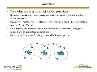
Switching
Switching. Links. Strowger Timeline Ed Piskor's Comics & Stories, comics EE489 Telecommunication Systems Engineering Google Image http://privateline.com/ http--www.aueb.gr-Users-courcou-courses-regulation-lectures-l1-REGintro.pdf


Switching
E N D
Presentation Transcript
Links • Strowger Timeline • Ed Piskor's Comics & Stories, comics • EE489 Telecommunication Systems EngineeringGoogle Image • http://privateline.com/ • http--www.aueb.gr-Users-courcou-courses-regulation-lectures-l1-REGintro.pdf • http--www.eie.polyu.edu.hk-~shau-eie239_notes-student_notes-CommuSys.pdf • http--www.fcc.gov-oet-ea-presentations-files-oct05-Intro_to_FCC_Policy_GT.pdf • http--www.mut.ac.th-~apichan-EECM0461_intro.pdf
Switching • Why Switches • Switch History • Strowger • Step Switches • ESS • SS7
Why Switches • Tough lecture to finish? • Math –Mesh topology N(N-1)/2 • Switchboards- Manpower intensive • Boys • Girls on Rollerskates • Dress codes and Queen Bees • Which do you automate first?
Switch Timeline • See Handout.
Strowger switches • Almon Strowger – Funeral Director • Stepping switches corresponding to on off pulses generated by a dial phone. • Moves up and down and then rotated to another set of ten contacts giving you 100 choices. • Used until the Crossbar electo-mechanical switch was invented.
Crossbar Switch • Electromechanical switch with a matrix of vertical and horizontal bars and simpler motions, that worked more reliably. • Two dimensional array X-Y Rocked up and down by electromagnets had wire fingers with contacts beneath the bars connect to make the calls. • The first design of what is now called a crossbar switch was Western Electric's "coordinate selector" of 1915. It was little used in America, but the LM Ericsson company used an improved version for rural exchanges in Sweden.
Crossbar Switch • The system design used in AT&T's 1XB crossbar exchanges, which entered revenue service from 1938, was developed by Bell Telephone Labs. • Several millions of urban 1XB lines were installed from the 1950s in the United States
Panel Switches • The "Bell System" (Western Electric) never liked the idea of allowing customers to dial their own calls. • First Panel switch was installed in the early 1920's in Omaha, Nebraska and others were installed throughout the 20's and 30's in most metropolitan areas in the USA (except for Los Angeles, used step by step to be compatible with surrounding independent telephone companies).
Panel Switches • Step by Step work well in small communities • Limitations due to its direct control design and small # of connecting circuits that could connect to other subscribers in the same switch or other switches • Panel switch was the first telephone switch to use a concept of “store and forward” by use of a device called a “sender” which can store a number and then act upon the dialed number to route the call the best way possible.
Panel Switches • Most Panel offices were removed from service by the late 1970's, though there is a rumor that the last Panel office in service was located in northern New Jersey and was removed in the early 1980's.
Electronic Switching System • First large scale Stored Program Control (SPC) telephone exchange OR ESS. • Introduced in Succasunna, NJ - May 1965 • switching fabric was composed of reed matrixes controlled by wire spring relays • In turn were controlled by a (CPU).
5ESS • The 5ESS Class 5 Switch first appeared in Seneca, Illinois (815 Area Code) in 1982 • replaced the 1ESS switch and other electromechanical and analog systems in the 1980s and 1990s. • Approximately half of all U.S. telephone exchanges are serviced by 5ESS switches.
Signaling System Number 7 • SS7 set of telephony signaling protocols which are used to set up most of the world's public switched telephone network telephone calls. • main purpose is to set up and tear down telephone calls • Other uses include number translation, prepaid billing, short message service (SMS), and a variety of other mass market services.
5ESS three main modules • Admin Module contains the central computers • Communications Module, which is the central time-divided switch of the system • Switching Module which in most exchanges is the majority of equipment. SM performs multiplexing, analog/digital coding, and other work to interface with the outside world. Each has a controller, a small computer whose CPUs and memories, like most common equipment of the exchange, are duplicated for redundancy.
SS7 • SS7 Benefits • Improves network efficiencies with fast call setup and refined call control. • Increases information transfer and flexibility for call connections. • Makes efficient use of voice trunks because the signaling path is separate from the voice path. • 24x7 state-of-the-art monitoring system for assured network reliability.
SS7 Components • Signal Transfer Points – Routes signals between databases and COs. • Service Switching Points – Software and ports in COs that enable switches to query DBs. • Service Control Points – Specialized DBs w/ billing and customer service information.
SCP What does it look like? SCP SCP CO SSP STP STP CO SSP CO SSP
Also connected to submarine cables and satellite links. PSTN Hierarchy International Exchanges National Exchanges Regional Exchanges Primary Switching Centres Local Exchanges, or Central Offices (C.O.’s)
Network Architecture Customer terminals 20% Outside plant, cables 29% Switching equipment 25% Multiplexing and Transmission equipment 15% Buildings, land, other 11%
Establishing A Call (Conventionally) • Calling customer takes phone off hook which closes the circuit to the C.O. (“looping the circuit”). • C.O. detects the “loop” and indicates readiness with dial tone. • Calling customer hears dial tone and dials number. • The network converts (“translates”) the phone number to a physical equipment address • The network checks on the called party status and decides on a routing for the connection. • If connection possible, the called party is alerted. • Large 20 Hz alternating current is applied to line (“ringing current”). • “Ring tone” is returned to the caller. • The called party picks up the handset and closes his/her loop. • Exchange detects second loop and “trips” or stops ringing, then establishes call. • One party opens loop by hanging up, and exchange clears connection.
Loop and Disconnect Signalling “pulse dialling” : • Line is rapidly disconnected and reconnected in sequence with one pulse for digit value “1”, two pulses for digit value “2”, etc. • Each pulse lasts 0.1 second. • Inter-digit pause (IDP) must be >0.5 second. • If not, current digit may combine with previous digit. • Ten digit phone number typically takes 6-15 seconds total. • This is the kind of signalling old “rotary dial” phones produced.
Dual-Tone Multi-Frequency Signalling DTMF signalling” or “tone signalling”. • Faster than pulse dialling (1-2 seconds for ten digit number). • Reduces call set-up time. • Each digit produced by combination of 2 pure frequency tones. • Reduces chances of error or interference.
Address Signalling Dial Pulsing Dual-Tone Multi-frequency (DTMF)
Special Link http://www.techtionary.com/ SS7 demonstration Switch Crossbar 0Circa 1936 Strowger step by step switch