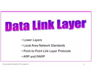
Point-to-Point Protocol Data Link Layer Loopback ARP and RARP
Data Link Layer II. Point-to-Point Protocol Data Link Layer Loopback ARP and RARP. Orientation. We are still talking about the Data Link Layer. Last Lecture we discussed protocols in broadcast LAN networks. Orientation 2.

Point-to-Point Protocol Data Link Layer Loopback ARP and RARP
E N D
Presentation Transcript
Data Link Layer II Point-to-Point Protocol Data Link Layer Loopback ARP and RARP
Orientation • We are still talking about the Data Link Layer. • Last Lecture we discussed protocols in broadcast LAN networks.
Orientation 2 • We learned that in broadcast LANs, the Link Layer is divided in two sublayers: • Media Access Control (MAC) • Logical Link Control (LLC) • We discussed the IEEE 802 family of LAN standards: 802.3 CSMA/CD (Ethernet) 802.4 Token Bus 802.5 Token Ring
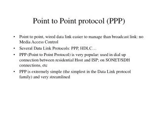
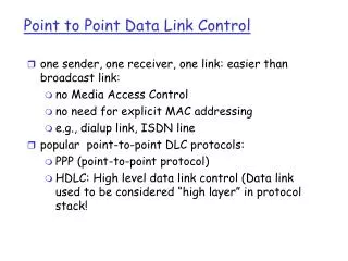
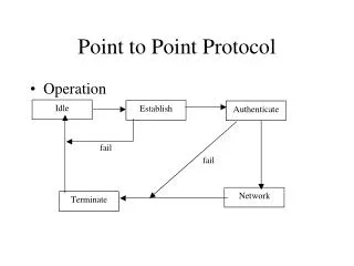
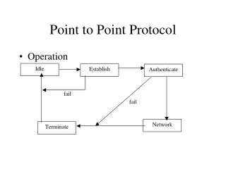
PPP - Point-to-Point Protocol • The PPP protocol is a data link protocol for transmission on a serial link. • Currently, most ISPs offer Internetaccess to dial-in users over PPP. • The main purpose of PPP isencapsulation of IP datagrams, but it can be used for other network protocols as well. • PPP was proposed in 1992; a predecessor of PPP was the Serial Link IP (SLIP) protocol.
PPP - IP encapsulation • PPP suports an asynchronous link (8 data bits/no parity) or a bit-oriented synchronous link. • The frame format of PPP is similar to the 802.2 LLC frame format: 296 if low delay
PPP - Escape sequences • If a data byte is 0x7e, how does the receiver know whether this is the end of a PPP frame or if it is a data byte? • PPP on synchronous links • Hardware bit stuffing is used to handle this • PPP on asynchronous links • Escape sequences are used • The byte 0x7e is transmitted as the 2-byte sequence 0x7d, 0x5e • The byte 0x7d is transmitted as the 2-byte sequence 0x7d, 0x5d
PPP - Link Control Protocol • The link control protocol (LCP) of PP is responsible for establishing, configuring, and negotiating the data-link connection. • LCP is specified in RFC 1331.
PPP Network Control Protocol • For each network layer protocol supported by PPP, there is one network control protocol (NCP). • The NCP for IP is specified in RFC 1332.
Loopback Interface • Most TCP implementations have a loopback interface with IP address 127.0.0.1 and namelocalhost. • The localhost behaves as a separate data link interface. • A packet that is sent to the loopback interface moves down the protocol stack and is returned back by the driver software for the localhost “device”. • Used for debugging, but also for multicasting and broad-casting.
Maximum Transmission Unit • The frame size limit of the data link protocol translates itself to a limit on the size of the IP datagram that can be encapsulated. • This limit is called maximum transmission unit (MTU). • MTUs for various data link layers: Ethernet: 1500 FDDI: 4352 802.3: 1492 ATM AAL5: 9180 802.5: 4464 PPP: 296 • What if the size of an IP datagram exceeds the MTU? IP datagram is fragmented into smaller units. • What if the route contains networks with different MTUs?
ARP and RARP • The IP protocol uses 32-bit addresses. • Data link protocols (Ethernet, FDDI, ATM) may have different (MAC) addresses. • The ARP and RARP protocols perform the translation between IP addresses and MAC layer addresses. • We will discuss ARP for broadcast LANs, particularly Ethernet LANs.
Address Translation (1) HOST-A wants to send an IP datagram to HOST-B. (2) HOST-A broadcasts an ARP request to all stations on the network: “What is the hardware address of HOST-B?” (3) HOST-B responds with an ARP Reply which contains its hardware address. (4) HOST-A transmits the IP datagram to HOST-B.
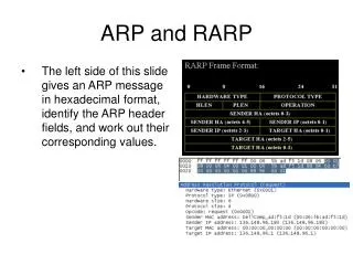
28 byte ARP request/reply Ethernet header Ethernet Dest Ethernet Source frame type hw type prot type hw size prot size op fld. sender Eth. addr sender IP addr target Eth. addr target IP addr 6 6 2 2 2 1 1 2 6 4 6 4 ARP Packet Format • Ethernet destination: ff:ff:ff:ff:ff:ff is broadcast address • Ethernet Source address: That of ARP request sending host • frame type: “0x0806” for ARP request/reply • hw type: “1” for Ethernet MAC addresses • prot type: “0x0800” for IP addresses • hw size, prot size: size of the respective address in bytes. • Op field: 1 = ARP request 2 = ARP reply 3 = RARP request 4 = RARP reply • Interesting: Both your textbook and RFC 826 do not mention a CRC field at the end of an ARP frame
ARP reply • The ARP reply is sent by the node whose IP address matches the address in the target IP address field of the ARP request • It fills its MAC address into the target Ethernet address field of the ARP request • It then swaps the two sender addresses (Ethernet and IP addresses) with the two target addresses, sets the op field to 2, and sends the ARP reply • The ARP reply is sent back to the source host only • All other nodes receiving the broadcast ARP ignore the request (since their IP addresses do not match the address that is being resolved)
Example with tcpdump 10:58:15.255050 0:0:86:7:4d:a9 Broadcast arp 60: arp who-has aida.poly.edu tell rigoletto.poly.edu 10:58:15.255182 0:80:c6:ff:9:99 0:0:86:7:4d:a9 arp 60: arp reply aida.poly.edu is-at 0:80:c6:ff:9:99 10:58:15.255671 0:0:86:7:4d:a9 0:80:c6:ff:9:99 ip 60: rigoletto.poly.edu.1042 > aida.poly.edu.telnet: S 6219463:6219463(0) win 8192 <mss 1460> (DF)
ARP Cache • Clearly, sending an ARP request/reply for each IP datagram is inefficient. • Each station maintains a cache (ARP Cache) of current entries. The entries expire after 20 minutes. • Everytime the ARP cache is consulted for a MAC address, the expiry timer is reset in common implementations. • ARP cache of aida.poly.edu: dibner-gw.poly.edu (128.238.42.1) at 0:0:c:1:a2:e ebbets.poly.edu (128.238.42.29) at 8:0:20:7a:da:44 mng.poly.edu (128.238.42.105) at 0:60:8:3:93:41 aida.poly.edu (128.238.42.114) at 0:80:c6:ff:9:99 permanent mare.poly.edu (128.238.42.247) at (incomplete)
Things to know about ARP • What happens if an ARP Request is made for a non-existing host? Several ARP requests are made with increasing time intervals between requests. Eventually, ARP gives up. • What if a host sends an ARP request for its own IP address? The other machines respond (gratuitous ARP) as if it was a normal ARP request. This is useful for detecting if an IP address has already been assigned. • Routers can respond to an ARP request for a host that is on a different subnet (Proxy ARP)
Proxy ARP • Router answers an ARP request on one of its networks for a host on another of its networks • netb answers as a “proxy” for sun.
RARP - Reverse ARP • Reverse ARP (RARP) performs a translation from a physical (MAC) address into a logical (IP) address. • When does one need RARP? Hosts without secondary storage (e.g., X- terminals) do not know their IP address when they are booted. • Packet format is the same as in ARP: • frame type: “0x0806” for ARP request/reply • Op field: 3 = RARP request 4 = RARP reply
Example from Textbook • A diskless host with name “sun” boots up: 1 . 0.0 8:0:20:3:f6:42 ff:ff:ff:ff:ff:ff rarp 60: rarp who-is 8:0:20:3:f6:42 tell 8:0:20:3:f6:4This is the broadcast RARP request 2 . 0.13 0:0:c0:6f:2d:40 8:0:20:3:f6:42 rarp 42: rarp reply 8:0:20:3:f6:42 at sun This is the response which contains the complete IP address 3 . 0.14 8:0:20:3:f6:42 0:0:c0:6f:2d:40 ip 42: sun.26999 > bsdi.tftp: 23 RRQ “8CFC0D21.SUN4C” Request to setup an TFTP read-request for bootstrapping.
Hub vs. switch • An ethernet hub simply broadcasts frames received on any one port to all other ports • An ethernet switch learns (knows) the MAC addresses of its hosts on all its ports and sends a frame received on one port to only the link connected to the destination of the frame • Multiple hosts can send frames into the ethernet switch at the same time; if two packets arriving simultaneously at a switch are destined to the same output port of the switch, one will be buffered while the other is transmitted