BRAKE HYDRAULIC SYSTEMS
510 likes | 598 Vues
Explore how hydraulic brake systems work, the role of pressure, piston size, and hydraulic fluids. Learn why correct sizing and pressure are crucial for optimal brake performance. Real-world cases shed light on the consequences of incorrect brake component sizing.

BRAKE HYDRAULIC SYSTEMS
E N D
Presentation Transcript
94 BRAKE HYDRAULIC SYSTEMS
Figure 94-1 Hydraulic brake lines transfer the brake effort to each brake assembly attached to all four wheels.
Figure 94-2 Because liquids cannot be compressed, they are able to transmit motion in a closed system.
Figure 94-3 Hydraulic system must be free of air to operate properly. If air is in the system, the air is compressed when the brake pedal is depressed and the brake fluid does not transmit the force to the wheel brakes.
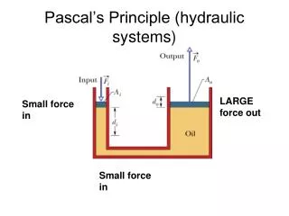
Figure 94-4 A one-pound force exerted on a small piston in a sealed system transfers the pressure to each square inch throughout the system. In this example, the 1-lb force is able to lift a 100-lb weight because it is supported by a piston that is 100 times larger in area than the small piston.
Figure 94-5 The amount of force (F) on the piston is the result of pressure (P) multiplied by the surface area (A). In this example, the driver is applying a force of 150 pounds but through the mechanical advantage of the brake pedal (3.3 to 1 ratio), the force is increased to 500 pounds into the master cylinder.
Figure 94-6 Drum brake illustrating the typical clearance between the brake shoes (friction material) and the rotating brake drum represented as the outermost black circle.
Figure 94-7 The brake pad (friction material) is pressed on both sides of the rotating rotor by the hydraulic pressure of the caliper.
FREQUENTLY ASKED QUESTION: How Much Brake Fluid Is Moved When the Brake Pedal Is Depressed? During a typical brake application, only about 1 teaspoon (5 ml or cc) of brake fluid actually is moved from the master cylinder and into the hydraulic system to cause the pressure buildup to occur.
Figure 94-8 Mechanical force and the master cylinder piston area determine the hydraulic pressure in the brake system.
Figure 94-9 Hydraulic pressure is the same throughout a closed system and acts with equal force on equal areas.
Figure 94-10 Differences in brake caliper and wheel cylinder piston area have a major effect on brake application force.
Figure 94-11 The increase in application force created by the large brake caliper piston is offset by a decrease in piston travel.
REAL WORLD FIX: Bigger Is Not Better A vehicle owner wanted better braking performance from his off-road race vehicle. Thinking that a larger master cylinder would help, a technician replaced the original 1-in.-bore-diameter master cylinder with a larger master cylinder with a 1 1/8-in.-bore-diameter master cylinder. After bleeding the system, the technician was anxious to test-drive the “new” brake system. During the test-drive the technician noticed that the brake pedal “grabbed” much higher than with the original master cylinder. This delighted the technician. The owner of the vehicle was also delighted until he tried to stop from highway speed. The driver had to use both feet to stop! The technician realized, after the complaint, that the larger master cylinder was able to move more brake fluid, but with less pressure to the wheel cylinders. The new master cylinder gave the impression of better brakes because the fluid was moved into the wheel cylinders (and calipers) quickly, and the pads and shoes contacted the rotor and drums sooner because of the greater volume of brake fluid moved by the larger pistons in the master cylinder. To calculate the difference in pressure between the original (stock) master cylinder and the larger replacement, the technician used Pascal’s law with the following results:
REAL WORLD FIX: Bigger Is Not Better (cont.)Original Master Cylinder Replacement Master Cylinder(1 in. bore) (1 1/8 in. bore)Pressure = Force / Area Pressure = Force / AreaPSI = 450 lb / Area (typical) PSI = 450 lb / Area (typical)Area = πr2 = 3.14 × .52 (1/2 of 1 in.) Area = πr2 = 3.14 × .56252 (1/2 of 1 1/8 in.)Area = 3.14 × .25 Area = 3.14 × .316Area .785 sq. in. Area .992 sq. in.Pressure = 450/.785 = 573 PSI Pressure = 450/.992 = 454 PSIThe difference in pressure is 119 PSI less with the larger master cylinder (573 - 454 = 119).The stopping power of the brakes was reduced because the larger diameter master cylinder piston produced lower pressure (the same force was spread over a larger area and this means that the pressure [PSI] is less).All master cylinders are sized correctly from the factory for the correct braking effort, pressure, pedal travel, and stopping ability. A technician should never change the sizing of any hydraulic brake component on any vehicle! [WDS PROBLEM - formula need fixed]
Figure 94-12 Typical master cylinder showing the reservoir and associated parts. The reservoir diaphragm lays directly on top of the brake fluid, which helps keep air from the surface of the brake fluid because brake fluid easily absorbs moisture from the air.
TECH TIP: Don’t Fill the Master Cylinder Without Seeing Me! The boss explained to the beginning technician that there are two reasons why the customer should be told not to fill the master cylinder reservoir when the brake fluid is down to the “minimum” mark, as shown in - FIGURE 94–13 . 1. If the master cylinder reservoir is low, there may be a leak that should be repaired. 2. As the brakes wear, the disc brake piston moves outward to maintain the same distance between friction materials and the rotor. Therefore, as the disc brake pads wear, the brake fluid level goes down to compensate. Therefore if the brake fluid is low, the vehicle should be serviced—either for new brakes or to repair a leak.
Figure 94-13 Master cylinder with brake fluid level at the “max” (maximum) line.
Figure 94-14 The typical brake pedal is supported by a mount and attached to the pushrod by a U-shaped bracket. The pin used to retain the clevis to the brake pedal is usually called a clevis pin.
Figure 94-15 The composite master cylinder is made from two different materials—aluminum for the body and plastic materials for the reservoir and reservoir cover. This type of reservoir feeds both primary (closest to the driver) and secondary chambers, and therefore uses a fluid level switch that activates the red dash warning lamp if the brake fluid level drops.
Figure 94-16 Note the various names for the vent port (front port) and the replenishing port (rear port). Names vary by vehicle and brake component manufacturer. The names vent port and replenishing port are the terms recommended by the Society of Automotive Engineers (SAE).
Figure 94-17 The vent ports must remain open to allow brake fluid to expand when heated by the friction material and transferred to the caliper and/or wheel cylinder. As the brake fluid increases in temperature, it expands causing the brakes to self-apply which is prevented by the open vent ports.
Figure 94-18 As the brake pedal is depressed, the pushrod moves the primary piston forward, closing off the vent port. As soon as the port is blocked, pressure builds in front of the primary sealing cup, which pushes on the secondary piston. The secondary piston also moves forward, blocking the secondary vent port and building pressure in front of the primary sealing cup.
Figure 94-19 The purpose of the replenishing port is to keep the volume behind the primary piston filled with brake fluid from the reservoir as the piston moves forward during a brake application.
TECH TIP: Too Much Is Bad Some vehicle owners or inexperienced service people may fill the master cylinder to the top. Master cylinders should only be filled to the “maximum” level line or about 1/4 in. (6 mm) from the top to allow room for expansion when the brake fluid gets hot during normal operation. If the master cylinder is filled to the top, the expanding brake fluid has no place to expand and the pressure increases. This increased pressure can cause the brakes to “self-apply,” shortening brake friction material life and increasing fuel consumption. Overheated brakes can result and the brake fluid may boil, causing a total loss of braking.
Figure 94-20 When the brake pedal is released, the master cylinder piston moves rearward. Some of the brake fluid is pushed back up through the replenishing port, but most of the fluid flows past the sealing cup. Therefore, when the driver pumps the brake pedal, the additional fluid in front of the pressure-building sealing cup is available quickly.
Figure 94-21 Rear-wheel-drive vehicles use a dual split master cylinder.
Always Check for Venting (Compensation)Whenever diagnosing any braking problem, start the diagnosis at the master cylinder—the heart of any braking system. Remove the reservoir cover and observe the brake fluid for spurting while an assistant depresses the brake pedal.Normal operation (movement of fluid observed in the reservoir)There should be a squirt or movement of brake fluid out of the vent port of both the primary and secondary chambers. This indicates that the vent port is open and that the sealing cup is capable of moving fluid upward through the port before the cup seals off the port as it moves forward to pressurize the fluid.No movement of fluid observed in the reservoir in the primary pistonThis indicates that brake fluid is not being moved as the brake pedal is depressed. This can be caused by the following: a.Incorrect brake pedal height—brake pedal or pushrod adjustment could be allowing the primary piston to be too far forward, causing the seal cup to be forward of the vent port. Adjust the brake pedal height to a higher level and check for a too-long pushrod length. b. A defective or swollen rubber sealing cup on the primary piston could cause the cup itself to block the vent port.NOTE: If the vent port is blocked for any reason, the brakes of the vehicle may self-apply when the brake fluid heats up during normal braking. Since the vent port is blocked, the expanded hotter brake fluid has no place to expand and instead increases the pressure in the brake lines. The increase in pressure causes the brakes to apply. Loosening the bleeder valves and releasing the built-up pressure is a check that the brakes are self-applying. Then check the master cylinder to see if it is “venting.”
Always Check for Venting (Compensation)Whenever diagnosing any braking problem, start the diagnosis at the master cylinder—the heart of any braking system. Remove the reservoir cover and observe the brake fluid for spurting while an assistant depresses the brake pedal.Normal operation (movement of fluid observed in the reservoir)There should be a squirt or movement of brake fluid out of the vent port of both the primary and secondary chambers. This indicates that the vent port is open and that the sealing cup is capable of moving fluid upward through the port before the cup seals off the port as it moves forward to pressurize the fluid.No movement of fluid observed in the reservoir in the primary pistonThis indicates that brake fluid is not being moved as the brake pedal is depressed. This can be caused by the following: a.Incorrect brake pedal height—brake pedal or pushrod adjustment could be allowing the primary piston to be too far forward, causing the seal cup to be forward of the vent port. Adjust the brake pedal height to a higher level and check for a too-long pushrod length. b. A defective or swollen rubber sealing cup on the primary piston could cause the cup itself to block the vent port.NOTE: If the vent port is blocked for any reason, the brakes of the vehicle may self-apply when the brake fluid heats up during normal braking. Since the vent port is blocked, the expanded hotter brake fluid has no place to expand and instead increases the pressure in the brake lines. The increase in pressure causes the brakes to apply. Loosening the bleeder valves and releasing the built-up pressure is a check that the brakes are self-applying. Then check the master cylinder to see if it is “venting.”
Always Check for Venting (Compensation)Whenever diagnosing any braking problem, start the diagnosis at the master cylinder—the heart of any braking system. Remove the reservoir cover and observe the brake fluid for spurting while an assistant depresses the brake pedal.Normal operation (movement of fluid observed in the reservoir)There should be a squirt or movement of brake fluid out of the vent port of both the primary and secondary chambers. This indicates that the vent port is open and that the sealing cup is capable of moving fluid upward through the port before the cup seals off the port as it moves forward to pressurize the fluid.No movement of fluid observed in the reservoir in the primary pistonThis indicates that brake fluid is not being moved as the brake pedal is depressed. This can be caused by the following: a.Incorrect brake pedal height—brake pedal or pushrod adjustment could be allowing the primary piston to be too far forward, causing the seal cup to be forward of the vent port. Adjust the brake pedal height to a higher level and check for a too-long pushrod length. b. A defective or swollen rubber sealing cup on the primary piston could cause the cup itself to block the vent port.NOTE: If the vent port is blocked for any reason, the brakes of the vehicle may self-apply when the brake fluid heats up during normal braking. Since the vent port is blocked, the expanded hotter brake fluid has no place to expand and instead increases the pressure in the brake lines. The increase in pressure causes the brakes to apply. Loosening the bleeder valves and releasing the built-up pressure is a check that the brakes are self-applying. Then check the master cylinder to see if it is “venting.”
Figure 94-22 The primary outlet is the outlet closest to the pushrod end of the master cylinder and the secondary outlet is closest to the nose end of the master cylinder.
Figure 94-23 In the event of a primary system failure, no hydraulic pressure is available to push the second piston forward. As a result, the primary piston extension rod contacts the secondary piston and pushes on the secondary piston mechanically rather than hydraulically. The loss of pressure in the primary system is usually noticed by the driver by a lower-than-normal brake pedal and the lighting of the red brake warning lamp.
Figure 94-24 Front-wheel-drive vehicles use a diagonal split master cylinder. In this design one section of the master cylinder operates the right front and the left rear brake and the other section operates the left front and right rear. In the event of a failure in one section, at least one front brake will still function.
Figure 94-25 Quick take-up master cylinder can be identified by the oversize primary low-pressure chamber.
Figure 94-26 A brake pedal depressor like this can be used during a wheel alignment to block the flow of brake fluid from the master cylinder during service work on the hydraulic system.
TECH TIP: The Brake Pedal Depressor Trick The master cylinder can be used to block the flow of brake fluid. Whenever any hydraulic brake component is removed, brake fluid tends to leak out because the master cylinder is usually higher than most other hydraulic components such as wheel cylinders and calipers. To prevent brake fluid loss that can easily empty the master cylinder reservoir, simply depress the brake pedal slightly or prop a stick or other pedal depressor to keep the brake pedal down. When the brake pedal is depressed, the piston sealing cups move forward, blocking off the reservoir from the rest of the braking system. The master cylinder stays full and the brake fluid stops dripping out of brake lines that have been disconnected. - SEE FIGURE 94–26 .NOTE: Try this—put a straw into a glass of water. Use a finger to seal the top of the straw and then remove the straw from the glass of water. The water remains in the straw because air cannot get into the top of the straw. This is why the brake pedal depressor trick works to prevent the loss of brake fluid from the system even if the brake line is totally disconnected.
Figure 94-27 Some seepage is normal when a trace of fluid appears on the vacuum booster shell. Excessive leakage, however, indicates a leaking secondary (end) seal.
Figure 94-28 Pedal height is usually measured from the floor to the top of the brake pedal. Some vehicle manufacturers recommend removing the carpet and measuring from the asphalt matting on the floor for an accurate measurement. Always follow the manufacturer’s recommended procedures and measurements. (Courtesy of Toyota Motor Sales, U.S.A., Inc.)
Figure 94-29 Brake pedal free play is the distance between the brake pedal fully released and the position of the brake pedal when braking resistance is felt. (Courtesy of Toyota Motor Sales, U.S.A., Inc.)
Figure 94-30 Brake pedal reserve is usually specified as the measurement from the floor to the top of the brake pedal with the brakes applied. A quick-and-easy test of pedal reserve is to try to place your left toe underneath the brake pedal while the brake pedal is depressed with your right foot. If your toe will not fit, then pedal reserve may not be sufficient.
TECH TIP: Check for Bypassing If a master cylinder is leaking internally, brake fluid can be pumped from the rear chamber into the front chamber of the master cylinder. This internal leakage is called bypassing. When the fluid bypasses, the front chamber can overflow while emptying the rear chamber. Therefore, whenever checking the level of brake fluid, do not think that a low rear reservoir is always due to an external leak. Also, a master cylinder that is bypassing (leaking internally) will usually cause a lower-than-normal brake pedal.
Figure 94-31 Using a prybar to carefully remove the reservoir from the master cylinder.
Figure 94-32 Whenever disassembling a master cylinder, note the exact order of parts as they are removed. Master cylinder overhaul kits (when available) often include entire piston assemblies rather than the individual seals.
TECH TIP: WARNING Use extreme care when using compressed air. The piston can be shot out of the master cylinder with a great force, which could cause personal injury.
Figure 94-34 To reinstall the reservoir onto a master cylinder, place the reservoir on a clean flat surface and push the housing down onto the reservoir after coating the rubber seals with brake fluid.
Figure 94-35 Bleeding a master cylinder before installing it on the vehicle. The master cylinder is clamped into a bench vise while using a rounded end of a dowel rod to push on the pushrod end with bleeder tubes down into the brake fluid. Master cylinders should be clamped on the mounting flange as shown to prevent distorting the master cylinder bore.
Figure 94-36 Installing a master cylinder. Always tighten the retaining fastener and brake lines to factory specifications.