Overall Layout
This update provides the latest information on the overall layout, dimensions, and design of the LEReC Cooling Section components and equipment. It also includes details on the design of various magnets, vacuum chambers, and beam instrumentation.

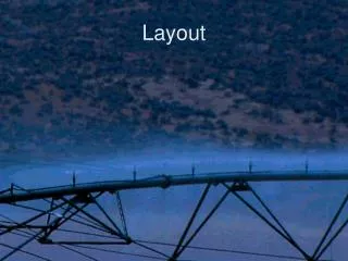
Overall Layout
E N D
Presentation Transcript
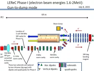
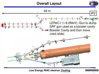
Overall Layout 64 m IP2 LEReC-I (1.6-2MeV): Gun to dump SRF gun used as a booster cavity Booster Cavity and Gun move (next slide)
LEReC Loop Dimensions Return loop length increased to 112. M
5 cell cavity location Location of egun and 5-cell, the beam line length and distance from IR center and tolerance, is being updated by R. Meier. 5 cell
Overall Layout 3.75”OD/3.62”ID beam line 9.2 cm ID 2.5”OD/2.38”ID beam line (6 cm ID) 5.0”OD/4.78”ID beam line 12 cm ID From: Fedotov, Alexei Sent: Friday, April 03, 2015 2:22 PMSubject: RE: LEReC Cooling Section Component Design Meeting 4 - 2 - 15 2.38” ID gives sufficient margin for the merger section (from one 20 deg. dipole to another). It is sufficient for beam transport line of LEReC Phase-I as well. However, to take into account LEReC Phase-II with higher charges, the area from the DC gun to the SRF booster and then additional area where for Phase II zig-zag will be needed from the SRF booster to the SRF 5-cell cavity should be revisited when choosing appropriate vacuum chamber size. Alexei
BPMs in Cooling Section (14 Locations) Orthogonal Installation – simple processing. Large Dia. BPM Housings (4.8 ID), 28mm buttons Drawings complete SOW and Spec complete. Requisition approved
Compensating and Matching Solenoids Contract Awarded: 9/15/2015 delivery for both Design support stand assembly – provide space for mu metal shields, separate beam pipe stand support. Magnetic shielding analysis (Wuzheng) Design prototype mu metal shields and supports. Magnet measurement fixture plan for prototype and design test fixtures.
Profile Monitors – New designs for Cooling Section Ferrite ring mounting point. Low power loss - CMD5005 material. Ferrite shape is not critical Peter re-analyzed the chamber. modeled is 1.65” OD, 1.45” ID and 1” high. Chamber design being finalized and detailed.
Profile Monitors – New designs for Cooling Section Utilize commercial vacuum linear feedthrough/drive system (D. Weiss) Need to adapt YAG screen/mirror holder and emittance slits to drive shaft. Create fabrication drawings for YAG screen/mirror holder and emittance slits
180o Dipole Magnet Magnetic field quality and repeatability for energy spread measurement. Test using CeC dipole complete(A. Jain) Meeting next week 02:00 with A. Jain (solid vs laminated) Need to add H corrector + LF quadrupole to the magnet. Range of motion for magnet core +/- 10cm. Magnet Vertical Gap = 10.0 cm (3.94 in.) Vacuum Chamber Aperture = 9.5 cm (3.75 in.)
Crossing tube aperture (3.94 in. vertical) Circular tube, vacuum Chamber ID = 9.5 cm (3.75 in.) Binping Xiao has completed analysis. Final review and approval (Alexei)
Vacuum Hardware Beam line bellows fabrication drawing in checking. 180 chamber fabrication drawing underway. 180 accordion bellows being designed.
20o Dipole Magnet Drawings checked – Spec/SOW approved (4/1/2015). Requisition approved SOW – 2 magnets by 10/1/2015. Out for Bid? Distance Between Pole Faces = 10.4 cm (4.1 in.) Magnet Vertical Gap = 10 cm Vacuum Chamber V Aperture = 9.5 cm (3.74 in.)
20o Dipole Magnet Vacuum Chamber Sent to Binping for analysis
LEReC Cooling Section Design Room Design 180o dipole chamber for impedance review (KH) LF & HF solenoid and 20o dipole fabrication drawings(KH) BPM chamber and buttons (VDM) Beam Line 5” bellows with shields fabrication drawings (GW) 20o dipole vacuum chamber for impedence review (KH) 180o dipole fabrication drawings (KH) Beam Instrumentation PM and ES drive fabrication drawings (GW and VDM) 180o dipole magnet and vacuum chamber integration + large sliding bellows (KH) Beam Instrumentation PM and ES Vacuum Chambers & ferrite insert (GW) Beam Instrumentation PM ferrite insert (GW) 180o and 20o dipole vacuum chamber (KH) 20o and 180o stand drawings (KH) Beam line solenoid stand LF Solenoid, BPM, and long pipe are to be independently positioned and surveyed on common stand. Magnetic Shielding drawing and solenoid magnetic measurement test station Cable tray and penetration drawings
LEReC Design Room Phase 2: 5 cell cavity positioning (RM) DC Gun Vacuum Chamber Fabrication Drawings (JH) DC Gun SF6 Pressure chamber specification control drawings (JH) Phase 2: 5 cell cavity positioning (RM) – Revised Position Phase 1 and 2 cryogenic system layout (RM) DC Gun stands (JH) DC Gun cathode insertion drive 2.1 GHz warm cavity specification control drawings 704 MHz warm cavity specification control drawings DC Gun to Booster SRF booster cavity beam line DC Gun cathode coating system upgrade – coating system vacuum chamber Transport line layout drawing (RM/VDM)
Sector 2 Modifications Move cable tray Modify cable tray Move Access Controls Gate Remove stairway and part of cross-over platform
Sector 1 Relocation Remove/relocate cables: instrumentation, cryogenics, vacuum, power Move cable trays