
Conceptual Design in Manufacturing Logistics: Deliverables & Approach Overview
E N D
Presentation Transcript
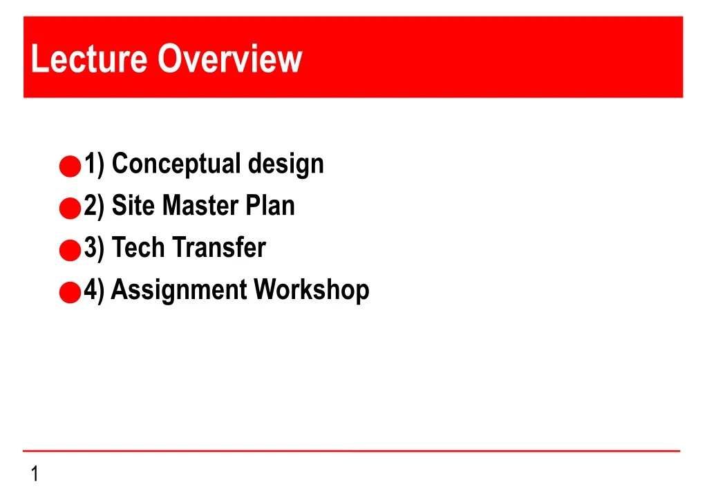
Lecture Overview • 1) Conceptual design • 2) Site Master Plan • 3) Tech Transfer • 4) Assignment Workshop
Conceptual Design What is Conceptual design? • Result of many hours brainstorming, discussion….. • Formal and structured document • Fact not fiction
Conceptual Design Definition/ Purpose • First and real quantified attempt to size, shape, program and cost an investment • Provides a robust basis for investment decisions • Key element in feasibility study • Assists in facility location decisions • Basis for assessing local infrastructure • Basis for detailed design
Conceptual Design Approach • The process is key - start with the process and provide optimal conditions • Develop batch philosophy, sizing, frequency and throughput for all stages • Size process elements and define space and servicing requirements • Design outwards from process elements to other disciplines e.g. utilities, HVAC, E&I, Civil/ Structural/ Architectural • Manage a coordinated design approach across all disciplines • Collect/ collate disciplinary input for cost estimation
Conceptual Design Manufacturing Logistics • Essential as a good basis for concept • Full scale study begins with dose form and market projection based on annual patient dose and patient population • Move backwards through doses, packs, lyo load, fill rate, formulation batch size, vessel size and number, innoculum, seeding etc to sees what’s required to meet the target (always allow a safety factor) • Allow for qualification, cleaning, downtime, decontamination, shifts, maintenance etc. in study • Move outwards from core process through CIP, Process Utilities, General Utilities etc
Conceptual Design Deliverables from Conceptual Design • Process descriptions and PFD’s (Process flow Diagrams) (not P&ID’s) • Equipment Lists, schedules and outline specs • Layouts and sections with classifications • Material and personnel flow studies • cGMP review • HVAC schematic and philosophy • Schematic for clean and general utilities • Electrical load calculations and SLD • Controls philosophy • Cost estimate +/- 25% (typical) • Project Schedule • Site Plan
Conceptual Design Optional Deliverables • Planning Package • Selected Equipment Specifications • Long Delivery PO’s • Negotiations with utilities providers • Validation Master Plan • Validation input on long delivery items
Conceptual Design Develop Process • Remember the core purpose of the facility is to accommodate a process or processes • ‘Process’ can be fermentation, DSP, formulation, fill finish or even packaging • A robust process with known output requirements is a basic prerequisite • PFD’s are first Engineering Description of Process • Good PFD’s will show: • Equipment with sizes/ duties • Flows • Material Balances • Sequence/ Timings/ Durations • Cleaning/ Process Utilities needs
Conceptual Design Equipment • Process equipment list is a critical document – for planning, layout, costing etc • Key equipment sized from manufacturing logistics and batch sizing (what is it required to do?) • Early vendor input is beneficial • Size and shape of equipment needed for concept stage • Configuration of process areas is based on equipment sizing and access requirements • Decisions on ‘state of the art’ technology or older proven technology
Conceptual Design Critical Utilities • Start with process utilities and direct impact systems • Includes RO, WFI & Clean Steam • Can also include CIP (may be part of process) • Size and shape of generation plant, storage and distribution • Other than CIP, which is integrated, most critical utilities need to be close/ adjacent
Conceptual Design HVAC & Classification • Critical in most areas of typical aseptic facility - more so in fill finish • Have the classification discussions/ decisions early • In essence, HVAC plant and distribution need to be adjoining to area served • HVAC, classifications are major determinant of ultimate layout and indeed of most utilities
Conceptual Design Layers • Apply layering concept • Layers roughly correspond to classifications • ‘Core’ is where critical process takes place • In multi process facilities, there may be multiple cores • Adjacent layers – reduced need for proximity • Remote layers – not proximity dependent
Conceptual Design Preliminary Layouts • Developed on ‘core outward’ basis • Classifications are critical - classification drawings needed • Protection of process core areas – airlocks and garbing • Define pre and post inactivation • Separate entry and exit may be needed • Return corridors • Decontamination areas • Corridors critical – these can dictate classifications
Conceptual Design Process Layouts • Sensible spacing • Common sense flow patterns • Ordered configuration • Access for Materials, Personnel, Maintenance • Engineering Aesthetics • Flow Priorities are: • Materials • Personnel • Fluids • Cable systems
Conceptual Design Buffer Make-up • Biggest material movements in bulk processing • Should be adjacent to formulation • Generally larger overall volumes than core process • May require material handling, dust control etc • Sterile filtered at this point
Conceptual Design Clean Utilities & CIP • CIP/ SIP are integral parts of a process design • WFI generation, storage and loop distribution • Clean Steam generation & distribution • Significant space required • CIP circuits should be as short as possible/ integrated – design for gravity return where possible
Conceptual Design Access & Communications Corridors • Keep material movements under cover • Link corridor preferred – also favour straight spine with buildings either side • Warehouse is focal here – more so for fill/ finish than bulk • Personnel facilities are important – significant time losses in canteen or rest room trips (smoking areas?) • Also truck access to be addressed • Link corridor may be at 2 levels
Conceptual Design Warehouse/ Material Movements • Calculate number of pallets - no shortcuts here as operations are specific • Minimum level for large plant is narrow aisle with 7-8 pallets high - requires 0.5 m2 per pallet • Traditional low profile needs 2.0m2 per pallet • Decisions on receiving/ dispatch, sampling, dispensing etc • Warehouse configuration drives site layout
Conceptual Design Personnel Movements • Essential personnel only close to process (balance garbing and accommodation costs against proximity) • Secondary/ tertiary garbing must be close • Normal now to have separate in/ out flow passages • Separate primary change/ lockers/ toilets/ showers • Analyse movements – may justify multiple cafeterias, toilets, primary change areas
Conceptual Design Decisions on Height • Fill/ Finish height – usually single process floor • Bio facility ideally at least 3 floors: Process is sandwiched between HVAC and CIP (utilities) • Process utilities can be above, below or alongside • Two floor process drives us to 4 floor ideal (e.g. 12500L Vessel) • Warehouse height – min 12m • Admin & other heights based on footprint available
Conceptual Design Air Handling • Layouts and classification drive HVAC sizing • HVAC plant is a big space user – plant room footprint usually exceeds total process area (top floor) • Early decisions needed for walk-on concept, interstitial spaces etc • Care with intakes and exhausts – allow segregation • Decision re: LPHW or steam as heating medium • Don’t over specify humidity limits – costly • Smart recirculation policy based on energy efficiency • Separate once-through needed for ‘active’ spaces
Conceptual Design Utilities – General • Biggest user is HVAC – next is Process Utilities • Assess demands for these users • Size primary generation equipment – use modular approach >3 units • CUB (Central Utilities Building) concept now fairly universal • CUB usually remote to avoid interference with expansion plans • Smart planning for pipe racks and distribution
Conceptual Design Electrical • Size from load list and utilities requirement • Apply diversity factors based on experience • Locate MCC’s adjacent to loads • Decision on standby generation and scope • Assess local reliability and capacity • Policy on centralized versus distributed transformers • Consider renewable/ sustainable energy
Conceptual Design Controls & Automation • Early decisions on general principles: PLC vs. DCS • Similarly for scope of communication and networking • Avoid ‘nice to have’ items – can result in downstream complications • Similarly avoid ‘state of the art’ – usually untested and may result in unknown complications • Remember need for aseptic interfaces
Conceptual Design Finishes • Policy decision re: proprietary partition vs. traditional stud • Similar decisions for floors, ceilings, doors and windows • Again, remember Baselines Guides for economical solutions • Proprietary partitions cost significantly more – don’t be fooled • They can however save significantly in time, use of wet trades, disruption • They also look better (makes facility more impressive)
Clean Room Wall Make-Up STICK BUILT • Cold formed Metal stud frame system. • Gypsum plaster board • Plaster skim coat. • Spray applied STERIDEX paint system. • Wall protection. Advantages: • Theoretically more economical. Disadvantages: • Coordination of trades. • Wet & dusty construction. • Schedule impact Advantages: • Pre fabricated. • Quality control • Parallel work faces - Schedule advantage Disadvantages: • More expensive (Depending on system) • Integral wall protection. • Demountable. MODULAR • High pressure laminate. (Or steel panel) .
Conceptual Design Structure/ Civil • Design develops from layouts, height decisions, size, shape etc • Site structural capability needs to be assessed • Special requirements for super flat floors in warehouses etc • Integrate drainage requirements – all types • Site development, roads, car parks, landscaping • Remember special requirements e.g. Fire Protection, Earthquake etc
Conceptual Design Cost Estimate • Amount of effort depends on accuracy required • Process Equipment costs usually based on mix of vendor enquiries and engineers database • Process utilities normally costed on similar basis • Process piping based on estimated run length and composite unit costs can be factored • HVAC can be based on actual sizing costs for core areas and factored per square meter or cubic meter for others
Conceptual Design Cost Estimate (cont.) • Utilities costed on actual sizing and database costings • Distribution costed on estimated length and composite costs, or can be factored • Electrical costs based on points at various load sizes – derived from loads list • Field Instruments based on count and category – add a premium for aseptic quality • Automation costed based on I/O count • Extra added for special cGMP requirements e.g. GAMP and Part 11
Conceptual Design Cost Estimate (cont.) • Include for: • Professional design – Basic & Detailed • Validation – C&Q • Construction Management • Permitting • Client Internal Costs • Contingency
Conceptual Design Schedule • Critical aspect – must minimise time to market • Be realistic even though it’s years away! • Allow for decisions, approvals, • objections, contingencies • Allow for disruption and include constructability study • Beware of false assumptions on feasibility of existing site • Consult all parties early on and get agreement on big decisions
Conceptual Design Summary • Apply serious front end loading at concept stage • A poorly assembled concept can be a ‘milestone’ for later stages • Remember even the best estimates will omit some items – allow for unforeseen • On the other hand – don't kill it by being too conservative
Formulation & Vial Fill/ Finish Process FORMULATION ROOM 10 CONJ. BUFFER PREP MOBILE TRANSFER VESSEL MOBILE TRANSFER VESSEL FORMULATION VESSEL Transfer Room MANIFOLD F F VIAL FILLER WASHER DEPYRO TUNNEL VIALS REGIONAL PACKAGING VIAL STOPPER WARE- HOUSE SEMI AUTO VISION SYS CAPPER COLD STORE MANUAL PALLETIZER TRAY LOADER AUTO-VISION SYSTEM TRAYS
Formulation and Syringe Fill/ Finish Typical Output 200,000 Syringes Grade C Formulation Product Vessel AlPO4 Can Upload Buffer Make-Up Vessel Filter Buffer Hold Vessel Filter Conjugate Download Conjugate Pooling Vessel Filter 0.22 μm Filters 1 day Grade C E-Beam Grade A Room/ Isolator Grade D Filling & Inspection Surge Vessel Recirculation Tub Sterilisation Product Ready Product Vessel Automated Inspection Stoppering Filling 2 days
Syringe Filling Line Layout Elevation View INFEED ISOLATOR OUTFEED Plan View
E-Beam Process Plan GRADE C INFEED GRADE C SUPPLIED E-BEAM TUNNEL PRE-IRRADIATION GRADE A SUPPLIED E-BEAM TUNNEL POST-IRRADIATION +54Pa +44Pa +74Pa E-BEAM EXHAUST AIR FLOW MATERIAL FLOW POINT OF SURFACE DECONTAMINATION Plan View
Isolator and Outfeed Process Plan GRADE A DELID / DELINER GRADE A NESTED UDF FILL / STOPPERING GRADE A OUTFEED BUFFER GRADE C MOUSEHOLE UDF HIGH FLOW GRADE C BACKGROUND +84 Pa +84 Pa +84 Pa +54 Pa +54 Pa MATERIAL FLOW AIR FLOW WASTE FLOW Plan View