Adaptive Bulbous Bow for Inland Waterway Ships
290 likes | 308 Vues
This application case explores the use of an adaptive bulbous bow to reduce the total ship hull resistance in inland waterway ships, aiming to improve fuel consumption in shipbuilding. Computational fluid dynamics (CFD) computations and towing tests on scale models were conducted to analyze the effectiveness of different bulbous bow lengths. Results showed that the adaptive bulbous bow design can significantly decrease ship resistance within specific speed domains.

Adaptive Bulbous Bow for Inland Waterway Ships
E N D
Presentation Transcript
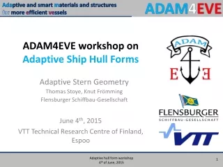
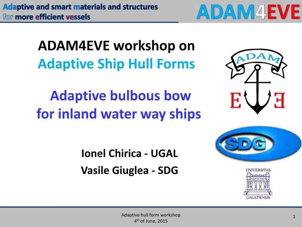
ADAM4EVE workshop on Adaptive Ship Hull Forms Adaptive bulbous bow for inland water way ships Ionel Chirica - UGAL Vasile Giuglea - SDG
Problem addressed The objective of the application case is to reduce the total ship hull resistance by integrating a bulbous bow into an inland water way ship. The reduction of fuel consumption is an important target of shipbuilding industry. In this respect, improving / reducing the total ship hull resistance and finding new solutions for ship hull forms is mandatory. The bulbous bow is an usual solution for sea going ships, facilitated by the concrete operational conditions (existence of a main operational condition, related to draught and speed).
In case of inland water ways ships, this main operational condition is difficult to be defined, due to the variation of certain parameters such as water dept, ship speed, current speed, etc.). As consequence, for inland water ways ships, is difficult to define a single bulb, able to cope with the variation of so many parameters. This was the reason to investigate the possibility to use a adaptive bulbous bow, with variable geometry, able to improve the total hull ship resistance, in different loading and navigational conditions.
Approach of the phenomenon The effect of the bulbous bow has been analyzed for a small passenger ship. The starting point: an existing ship, design by SDG, without bulbous bow. HSVA provided the design of the adaptive bulbous bow. The research have been performed in the following steps: - First step: CFD computation, performed for the initial configuration and for the ship with a bulbous bow of different lengths, to determine the total ship resistance. Four different bulbous bow lengths have been considered - 1875mm, 2000mm, 2250mm and 2500mm, for three relative ship speeds - 12km/h, 16km/h and 20km/h; - Second step: Design of mechanical system of the adaptable bulbous bow for the selected ship. - Third step: Towing tests on experimental scale model / prototype (1/10) The relative ship speeds considered: 10km/h; 12km/h, 14km/h; 16km/h, 18km/h; 20km/h; 22km/h
Technical solutions Initial ship Main dimensions: Length overall28.50 m Length waterline24.80 m Breadth 7.00 m Depth 3.00 m Draught 1.50 m - Towing tests on scale model (1/10) - CFD tests on full scale ship
Technical solutions • The experimental tests conditions: • ITTC Recommended Procedures 7.5-02-02-01; • during the experimental tests, the trim and the sinkage of the model were unrestricted; • the wave pattern was recorded and visually analysed; • the measured parameters: the model resistance, the sinkage, the trim angle of the model and the carriage speed; • all devices used for data acquisition (resistance dynamometer, sinkage and trim transducers) were calibrated before the tests; • the model tests results were extrapolated to the full-scale ship by using the ITTC 1957 ship-model correlation line, without blockage corrections (Froude method); • the ITTC 1957 formula was used in order to calculate the frictional resistance coefficient.
Technical solutions Details of experimental models and bulbous bow solutions Bare hull Bulb Ba Bulb B1 Bulb B2 Bulb B3
Technical solutions Experimental model tests have been performed in the Towing Tank of the University Dunarea de Jos of Galati, Romania, in order to determine the ship resistance performance.
Results The ship resistance diagram – bare hull Wave pattern, vs=18 Km/h.
Results The ship resistance diagram – hull with bulb Ba Wave pattern, vs=18 Km/h.
Results The ship resistance diagram – hull with bulb B1 Wave pattern, vs=18 Km/h.
Results The ship resistance diagram – hull with bulb B2 Wave pattern, vs=18 Km/h.
Results The ship resistance diagram – hull with bulb B3 Wave pattern, vs=18 Km/h.
Results Ship resistance diagrams - experiments Bare hull (I); Ba (II); B1 (III); B2 (IV); B3 (V)
Results Ship resistance diagrams - CFD
Results Full scale extrapolation. Comparative ship resistance values Used method: ITTC1957 ship-model correlation line, without blockage corrections.
Results Ship resistance diagrams - experiments Percentage values relative to Bare hull resistance
Results Comparative results: CFD-Towing tank experiments
Conclusions - At the minimum speed of 10 km/h, all the bulb solutions increase the ship resistance. - In the speed domain between 14-22 km/h, all the bulb solutions decrease the ship resistance. - The bulb (Ba) represents the best solution in the domain speed between 11-14 km/h. - The bulb (B1) represents the best solution in the domain speed between 14-22 km/h. - The maximum reduction (-14.46 %) of the ship resistance is obtained for the bulb (B1), at the speed of 16 km/h.
Conclusions Bulb efficiency
Videos Videos
Videos Bare hull: v=18km/h
Videos Ship model Ba: v=18km/h
Videos Ship model B1: v=18km/h
Videos Ship model B2: v=18km/h
Videos Ship model B3: v=18km/h
Final conclusion The step beyond: • The research performed in this WP is only the first step in the efficiency analysis of a bulbous bow for inland navigation ships. The limited budget and limited time did not allow to perform the full research. • To complete the research, many other parameters that affect the ship resistance should be considered: • various ship draughts (loading conditions); • various navigation conditions (water depth, channel breadth), etc.
Acknowledgements The Project is funded in the Seventh Framework Programme of the European Union • Contract No.: SCP2-GA-2012-314206