Today: Ideal versus Real elements: Models for real elements
Today: Ideal versus Real elements: Models for real elements Non-ideal voltages sources, real voltmeters, ammeters Series and parallel capacitors Charge sharing among capacitors, the paradox. i. i. Voltage drops if large current. + v . +. V BB. v. V BB. Real battery.
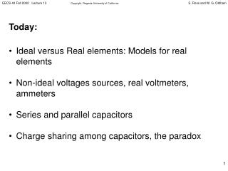

Today: Ideal versus Real elements: Models for real elements
E N D
Presentation Transcript
Today: • Ideal versus Real elements: Models for real elements • Non-ideal voltages sources, real voltmeters, ammeters • Series and parallel capacitors • Charge sharing among capacitors, the paradox
i i Voltage drops if large current + v + VBB v VBB Real battery MODELING NON-IDEAL VOLTAGE AND CURRENT SOURCES Two circuits are equivalent if they have the same I-V characteristic. A model of a device is a collection of ideal circuit elements that has the same I vs V characteristic as the actual (real) device (and is therefore equivalent). Example: A real battery What combination of voltage sources, current sources and resistors has this I-V characteristic?
i i Voltage drops if large current + v + VBB v VBB Real battery Approximation over range where i > 0: v = VBB iR i = (VBB v)/R (straight line with slope of -1/R) MODELING NON-IDEAL VOLTAGE AND CURRENT SOURCES Current-voltage characteristic of a real battery Simple resistor in series with ideal voltage source “models” real battery R + v i + - VBB Model of battery
REAL VOLTMETERSConcept of “Loading” as Application of Parallel Resistors How is voltage measured? Modern answer: Digital multimeter (DMM) Problem: Connecting leads from a realvoltmeter across two nodes changes the circuit. The voltmeter may be modeled by an ideal voltmeter (open circuit) in parallel with a resistance: “voltmeter input resistance,” Rin. Typical value: 10 MW Ideal Voltmeter Real Voltmeter Rin Model
+ But if a 1% error REAL VOLTMETERSConcept of “Loading” as Application of Parallel Resistors Computation of voltage(uses ideal Voltmeter) Measurement of voltage (including loading by real VM) R R 1 1 + - + + VSS VSS R V R R 2 2 2 in - - Example:
MEASURING CURRENT Insert DMM (in current measurement mode) into circuit. But ammeters disturb the circuit. Ammeters are characterized by their “ammeter input resistance,” Rin. Ideally this should be very low. Typical value 1W. Ideal Ammeter Real Ammeter Rin ? Model
MEASURING CURRENT Potential measurement error due to non-zero input resistance: I I meas ammeter R R 1 1 R in _ _ + + V V R 2 R 2 undisturbed circuit with ammeter Example: V = 1 V: R1 + R2 = 1 KW , Rin = 1W
C C + + IDEAL IDEAL Rin typically < 1 W DMM amps DMM amps DMM volts DMM volts Rin Rin C C + + MODEL OF REAL DIGITAL AMMETER MODEL OF REAL DIGITAL VOLTMETER Rin typically > 10 MW IDEAL AND NON-IDEAL METERS Note: Rin usually depends on current range Note: Rin may depend on range
V1 V2 | ( C2 C1 Ceq Equivalent to + + + i(t) i(t) | ( | ( Veq CAPACITORS IN SERIES Clearly,
+ | ( | ( C2 C1 i(t) V Equivalent capacitance defined by + | ( Ceq i(t) V(t) CAPACITORS IN PARALLEL Clearly,
CHARGE REDISTRIBUTION Pre-charged capacitor CA is connected to CB at t = 0 Let CA = CB = 1mF Find vA(t = 0+). From conservation of charge: QA (t>0) =QB (t>0) = ½QA (0) Thus vA (t>0) = ½ V From conservation of energy: ½ CA vA2(t>0) =½ CBvB2(t>0) =½ [½ CA vA2 (0)] so vA2(t>0) = [½ VA2 (0)] Or vA2(t>0) =½ t = 0 Initial Voltage = 0 Initial Voltage = 1V C C A B These answers are inconsistent. What is wrong with this circuit? Hint : We set up a paradox : Capacitor V jumps (infinite current so we dare not ingore the wire resistance)
initially uncharged + - t/t DIGITAL CIRCUIT EXAMPLE(Memory cell is read like this in DRAM) For simplicity, let CC = CB. If VC = V0, t < 0. Find VC(t), i(t), energy dissipated in R. VC/ V0 t/t
ENERGY DISSIPATION IN R TWO FACTS: (1) 1/2 of initial E lost (for CC = CB) (2) Independent of R!
initially uncharged + - Simple Proof of Energy Division For simplicity, let CC = CB. If VC = V0, t < 0. Find VC(t), i(t), energy dissipated in R. Thus initial Energy Stored in Capacitors is 1/2CCV02 + 0 Final Energy is 1/4 CCV02 so clearly the resistor dissipated the rest, independent of the value of the resistance. So even if the resistance is very, very, very small, it still dissipates half the energy in this example (where CC =CB).
L vX + vi(t) R v(t) V1 KVL: t t=0 i t THE BASIC INDUCTOR CIRCUIT t=L/R Solution has same form as RC! t 0 0
TRANSIENTS IN SINGLE-INDUCTOR OR SINGLE-CAPACITOR CIRCUITS - THE EASY WAY 1) Find Resistance seen from terminals of L or C (short voltage sources, open current sources). 2) The circuit time constant is L/R or RC (for every node, every current, every voltage). 3) Use initial conditions and inductor/capacitor rules to find initial values of all transient variables. (Capacitor voltage and inductor current must be continuous.) 4) Find t= value of all variables by setting all time derivatives to zero. 5) Sketch the time-behavior of all transient variables, based on initial and final values and known time constant. 6) Write the equation for each transient variable by inspection.