SPACECRAFT STRUCTURES
Learn about the process, design, and sources of loading for spacecraft structures and mechanisms. Understand the key considerations for developing reliable and efficient components for space missions. Discover the importance of strength, structural life, response, and natural frequency in spacecraft design. Explore the categories of primary, secondary, and tertiary structures and their unique requirements in the space environment.

SPACECRAFT STRUCTURES
E N D
Presentation Transcript
1- Introductionandkeyconsiderationsforspacecraftstructuresand mechanisms SPACECRAFT STRUCTURES 2- Process of developing spacecraft structures and mechanisms • 3- Sources of structural loading, ground and space environment effects 4- Structural analysis basics – we will discuss some in this course and you will learn more in other courses such as AE 462, AE 463, AE 464 etc. 5- Design of structures, types of structures and forms of construction, and materials (we will not discuss since you learn about different material forms in other courses) 6- Spacecraft mechanisms
1. INTRODUCTION AND KEY CONSIDERATIONS FOR SPACECRAFT STRUCTURES AND MECHANISMS • Emphasis will be on the cost-effective development of spacecraft structures and mechanisms • Development: Process that begins with defining the requirements and ends with delivering a product suitable for launch and operation • Design: Developing requirements, identifying options, doing analyses and trade studies, defining a product in detail • Cost-Effective: Getting high performance, reliability and confidence for money considering the knowns and uncertainities
SPACECRAFT • Space segment of a space mission such as a functional satellite • Information given here also applies to Launch vehicles Space transfer vehicles Re-entry vehicles • Size of spacecraft - Medium-Large: More analysis and tests are required (product variations are easier to control for larger structures,testing is not easy, test failures affect program) - Small-compact (small satellite): Less analysis can be performed and we can rely on more environmental tests to show the structure will satify the requirements (tiny circuit board; for small structures it is not easy to predict and assess structural loading)
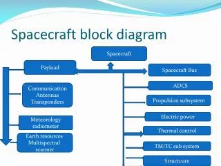
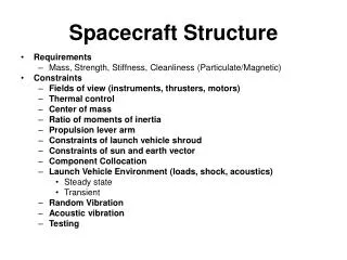
STRUCTURE OF A SPACECRAFT • Structures support key components in desirable locations considering, thermal control, fields of view for antennas and sensors, etc. • Stowed configuration must fit within the launch vehicles’s payload envelope • Structure protect the spacecraft components from dynamic environment during: ground operations, launch, deployment, mission operations • Structural vibration must not interfere with the launch vehicle’s control system • Spacecraft’s vibration in its deployed configuration must not interfere with its own control system • Materials used must survive ground, launch and on-orbit environments (time varying applied forces, pressure, humidity, radiation, contamination, thermal cycling etc.)
TYPICAL REQUIREMENTS FOR SPACECRAFT STRUCTURES • STRENGTH: Amount of load a structure can carry without rupturing • STRUCTURAL LIFE: Material fatigue and creep considerations • STRUCTURAL RESPONSE: Magnitude and duration of vibration in response to external loads • NATURAL FREQUENCY: Stowed configuration, on-orbit configuration • STIFFNESS: Allocated to substructures to achieve the required natural frequency for a larger assembly or to provide the necessary positional stability for a sensor or antenna
DAMPING: Dissipation of energy during vibration. • MASS PROPERTIES: Mass, mass moments, products of inertia, center of mass - Imposed by the launch vehicle and allocated to all subsystems - Allocated to substructures to achieve the required natural frequency for a larger assembly • DYNAMIC ENVELOPE: Imposed to avoid contact between two parts of the spacecraft under loads • POSITIONAL STABILITY: The ability to maintain location or orientation within a certain range. Concerns: thermo-elastic distortions, material yielding, shifting of mechanical joints. Derived to ensure critical instruments such as antennas, sensors will find their targets
MECHANICAL INTERFACE: The set of features such as flatness and locations of bolt holes that define how structures and components attach. Derived from designs of mating structures to ensure fit and avoid excessive deformations and loads
CATEGORIES OF STRUCTURES • PRIMARY STRUCTURES: Body structure, Launch vehicle adapter - Major load path between spacecraft’s component’s and launch vehicle - Usually designed for stiffness or natural frequency, and to survive the steady state accelerations and transient loading during launch • SECONDARY STRUCTURES: Appendage booms, support trusses, platforms, solar panels, antenna dishes - On-orbit thermal cycling, loads due to mission operations, acoustic pressure during launch can be more severe during launch • TERTIARY STRUCTURES: Brackets, electronic boxes (smallest structures) - High frequency base driven vibration causes the most severe loading Fatigue, stiffness and positional stability are the main driving requirements
3. SOURCES OF STRUCTURAL LOADING • A spacecraft’s structure’s on orbit performance such as pointing accuracy and positional stability can be important but environments; • On Earth • During launch • In space typically derive the designs of most structures • Structures must not only survive these environments but also protect the spacecraft’s non-structural components and allow them to function • The materials we select non-structural as well as structural must not degrade too much before and during mission
Ground testing is supposed to envelop mission environments with margin. Thus, to become confident that testing will be successful we must define test environments early and design our structures and mechanisms to withstand them. • In this section we will describe the types of environments a spacecraft may experience and concentrate on the sources of structural loading • Sources of structural loading - Static loadings: constant loads - Dynamic loads: loads that vary with time • Loads can be external and self-contained
- Static, external loads: * Weight of the supported components (gravity and steady acceleration) - Static, self-contained loads * pressure of stored propellant * mechanical preloads (springs, bolts etc.) * thermoelastic loads ( those generated by temperature changes) - Dynamic, external loads * engine thrusts * sound pressure * gusts of wind during launch * pulsed thrust to reposition a spacecraft on-orbit etc.
- Dynamic, self-contained loads: * Mass loading of a vibrating satellite during environmental testing or in space, after the force that caused the excitation is removed • Every event in the life of a spacecraft introduces structural loads: - Manufacturing - Ground handling - Testing - Transportation - Air transportation - Pre-launch preparations - Launch - Payload (spacecraft) separation - On-orbit operations - Landing (as applicable)
Note: - Launch vehicle terminology: payload means entire spacecraft - To a spacecraft: payload is the instrument or group of components that satisfies mission objectives • Launch generates the highest loads for most spacecraft structures; but any other event may be critical for parts of the structure • In many cases we can not control the loads; we have to estimate them and design the structure to withstand them • In this section load causing events will be addressed, and start with a relatively detailed look at launch which presents the most complex load causing environment
LAUNCH • Launch starts when the booster engines ignite and ends with the separation of the propulsion device that puts the spacecraft in its final orbit • A launch vehicle consists of stages shown in the following figure (configuration of a Delta II Launch vehicle)
LAUNCH • When the propellant from one stage is used up, the structure, storage tank, and engine of that stage separates from the launch vehicle, and engines of the next stage ignite. • This approach maintains efficiency by getting rid of unnecessary mass • The Space shuttle has two stages: - The solid rocket boosters separate early - The orbiter and external tank continue on at the second stage • The following figure shows axial acceleration for an Ariane launch vehicle versus time
LAUNCH Maximum Air Loads • As the vehicle approaches and passes through the speed of sound, shock waves form changing the aerodynamic pressures that act on the vehicle • These loads combine with - static air pressure - steady winds - wind shears and gusts - forces applied to stabilize and steer the booster • A launch vehicle bends as a beam under air loads • Payload may also carry some of this bending loads if it is attached to both booster core structure and payload fairing
LAUNCH Maximum Air Loads • Gusts and buffeting cause low frequency bending vibration in the booster/payload system generating lateral inertia loading • Variations in the sources of load may require that we evaluate several time periods to determine which cases are critical for structural design • Flight conditions that are most significant for the spacecraft may be different from those critical for the launch vehicle
LAUNCH Staging Events • Any time a rocket engine ignites or shuts down, the launch vehicle and payload experience a transient force • Axial acceleration during any stage builds as propellant is used up • The space shuttle throttles its engines to limit longitudinal acceleration to 3g’s but this is not typical for expendable vehicles • For some boosters, the slowly increasing axial acceleration before shutdown becomes so high that it alone can be a design driver • Shutdown and start-up of stages usually cause high transient loads. Therefore, these operations have to be negotiated with the payload engineers and launch vehicle supplier
LAUNCH Staging Events • Upper stages can be designed to start and stop several times as needed to get the spacecraft to a final orbit • At each successive engine start or shutdown, the mass is different so we may have to predict loads for several configurations • Once a stage is no longer used it separates from the launch vehicle; pyrotechnic devices fire to release the structural attachment • Often the pyro shock is the main concern with the separation event. Although shock seldom affects large structures it can damage electronics and can cause electro-mechanical devices to actuate
LAUNCH Payload Fairing Separation • Once a launch vehicle obtains enough altitude, the atmosphere becomes sparse enough so the payload no longer needs protection from aerodynamic forces and thermal effects • Therefore, fairings which are built in longitudinal segments separate with pyrotechnic devices. Thus, shock is a potential concern • Example: Titan IV consists of three 120 degree segments that separate radially, driven by bellows that rapidly expand when explosive devices ignite
LAUNCH Launch Load Factors for Preliminary Design • In the preliminary design of a spacecraft’s primary structure, we typically use load factors to represent the total loading environment at launch • The load factors of several launch vehicles are taken from the user guide of these vehicles • The following table shows load factors for several launch vehicles
Load factors and frequency requirements used in Preliminary Design
LAUNCH Launch Load Factors for Preliminary Design • The user guides caution that such load factors apply only if the spacecraft’s fundamental axial and lateral frequencies are above the values shown on the table • Most launch vehicles also have limits for the payload’s lowest natural frequency to ensure its dynamic characteristics don’t adversely affect the booster’s control system • Limitations of the load factors - They cover only steady-state accelerations, not the effects of acoustics, random vibration and shock - The load factors are not always high enough to envelope the effects of transients on secondary and tertiary structures that have modes of vibration below about 35-50 Hz
LAUNCH Launch Load Factors for Preliminary Design - Even for primary structures load factors may not be adequate, however they are useful for early design • Once we have reduced our design options for primary and secondary structures based on these loads we can start predicting loads to be used in detailed design
SPACE ENVIRONMENTS Classification of Earth Orbits
In this section we will describe the space environments, explain how they vary with altitude, and discuss the challenges they present for spacecraft structural design • Near Earth space environment consists of - Vacuum - Thermal radiation - Charged particle radiation (electrons, protons, ions) - Neutral atomic and molecular particles - Micrometeoroids and debris - Magnetic fields - Gravitational fields • First five of them are of most concern for material selection and structural design • During mission planning, we predict the intensity of each type of environment for the selected orbit.
Public-domain computer programs • These programs calculate environmental data for given orbital parameters
Vacuum • The following curve show the variation of pressure with altitude Atmospheric pressure on Earth is 760 torr
Vacuum • Most vacuum chambers used for testing operate in the range 10-3-10-8 torr • Vacuum levels at high orbital altitudes far exceed anything that can be achieved on Earth • At the low atmospheric pressures encountered in space, certain materials and lubricants breakdown and convert into a gas; this process is called outgassing Example: Materials, such as magnesium, outgas at such a high rate in the vacuum of space as not to be of any value for structural use
Vacuum • For spacecraft, outgassing has two undesirable effects: • It can cause certain key material properties to degrade • Gaseous emissions can condense on critical surfaces such as lenses, mirrors, sensors etc. Condensation on thermal coatings may also affect spacecraft’s thermal balance • Outgassing is addresses by: • Defining contamination budget for each spacecraft subsystem • By selecting materials that have acceptable levels of outgassing Note: Because wet lubricants have high levels of outgassing bearing etc. are typically sealed and proven techniques are used to control outgassing
Vacuum • As an example ASTM 595 specifies testing materials at 257oC in a vacuum of 10-5 torr for 24 hours. • For a material to pass this test the total mass loss must be no greater than 1% by weight • Another problem posed by space vacuum is that, because spacecraft are manufactured at ambient Earth pressure, any sealed structure will experience internal pressure of that level (1 atm) once in space • Such pressures can generate high pressures. To avoid explosion type failures we must: - design the enclosing walls to withstand this pressure - vent all closed spaces (holes are drilled in electronic boxes etc)
Vacuum • Honeycomb core in sanwich panels must be perforated to vent the inner cells • Desorption is another class of problem associated with space vacuum • Polymers used for adhesives and the matrix of composites tend to absorb water in humid environments causing expansion • Once in space, polymeric materials desorb the water causing the structure to contract: - The water can contaminate critical surfaces - Expansion and contraction can cause misalignments, so in design they must be accounted for
Thermal Radiation • Spacecraft temperatures depend on: - Internal heat generation - Heat emitted from spacecraft to deep into space - Heat absorbed by the spacecraft from the external sources • An orbiting spacecraft’s components have four external sources of heat: - Solar radiation - Albedo radiation (solar radiation reflecting from Planet’s surface) - Planetary emissions - Spacecraft emissions from heat generating components
Thermal Radiation • Thermal environments pose several problems for spacecraft designers. • Due to nonuniform heating and different materials expanding and contracting different amounts for a given temperature change, spacecraft structures distort under thermal environment • If we do not control these distortions, critical sensors and antennas may not be able to find their targets, and mechanisms may jam • Stresses caused by nonuniform heating and thermal distortions can result in structural failure or reduced structural life • Temperatures affect key properties of materials such as strength, stiffness, ductility etc.
Thermal Radiation • Most importantly, many of the spacecraft’s electrical and mechanical components will work only within certain temperature ranges • The purpose of a spacecraft’s thermal control subsystem is to maintain spacecraft temperatures within acceptable ranges: - Active thermal control: pumped liquid loops, heaters, refrigerators - Passive thermal control: Thermal blankets, radiators etc.