Download
1 / 33
330 likes | 449 Vues
Limited Streamer Tubes for the BaBar Instrumented Flux Return Upgrade. Changguo Lu, Princeton University On behalf of BaBar LST group. ICHEP’04, August 16-22, 2004 Beijing, P. R. China. Outline. BaBar IFR system Geometry selection – Choice of cell size

E N D
Limited Streamer Tubes for the BaBar Instrumented Flux Return Upgrade Changguo Lu, Princeton University On behalf of BaBar LST group ICHEP’04, August 16-22, 2004 Beijing, P. R. China ICHEP’04, Beijing Changguo Lu, Princeton University
Outline • BaBar IFR system • Geometry selection – Choice of cell size • Aging limit for two different graphite paints – MIBK(Methyl-Isobutyl-Ketone) based and water based paint • Characteristics of water based graphite paint – humidity sensitivity • LST failure modes – Self-sustaining discharge • Source scan test – powerful tool to check for surface defects • Remediation of LST’s with narrow plateaus – clean anode wire and negative HV treatment ICHEP’04, Beijing Changguo Lu, Princeton University
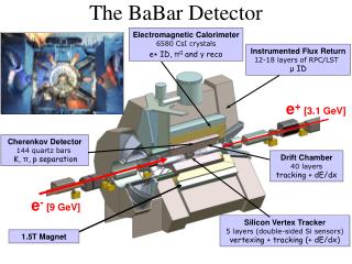
1: Present BaBar IFR system RPC efficiency degradation The efficiency of the RPC chambers in the BaBar Instrumented Flux Return (IFR) has seriously degraded, now averaging ~ 40%. At this point the additional ID information from the IFR is inadequate for some applications, and will be a serious problem in the future. After intensive investigation, various remediation efforts have been carried out, but without success. As a result the BaBar collaboration decided to replace the dying barrel RPC chambers about two years ago. ICHEP’04, Beijing Changguo Lu, Princeton University
Forward Endcap • 5 brass layers • New RPC’s to improve efficiency • Installed summer 2002 New RPC belt DWcm = 0.52 New layer DWcm = 0.23 10cm steel • Barrel • 6 Brass layers • RPC LST • 2 sectors in 2004 • 4 more in 2005 5 layers of 2.5 cm brass DWcm = 0.25 Upgrade of BaBar IFR ICHEP’04, Beijing Changguo Lu, Princeton University
Why BaBar choose LST to replace RPC? BaBar has chosen LST’sfor its barrel IFR system upgrade. The simplicity and low cost of RPC technology have resulted in more and more experiments choosing them over LST for similar applications. However, puzzling features of RPC behavior are still not understood. New and unresolved problems continue to emerge. Completely understanding the physics and chemistry of RPC operation won’t be in the scope of urgent BaBar decision making. LSTs are conceptually well understood and have been used in more than a dozen HEP experiments with generally good results. Successful prototype tests by ourselves have demonstrated robustness against the highest expected rates, and the integrated charge for the experimental lifetime. ICHEP’04, Beijing Changguo Lu, Princeton University
2: Choice of LST geometry • a single layer of big cells – 17 x 15 mm2 • a double layer of small cell – 9 x 8 mm2. (there is insufficient space for a double layer of 9x9 “standard” cell LST’s.) Double layers of small cell LST Single layer of large cell LST Compare several aspects of two options to select the better one. Due to the limited gap space (~22mm) available in the BaBar barrel IFR, we have two options to keep efficiency and reliability high: ICHEP’04, Beijing Changguo Lu, Princeton University
Comparison between two geometries • Large cell is not as sensitive as small cell to the anode wire displacement • Effect of anode wire diameter variation is similar. • Important advantages of large cell design: • fewer cells (30%) • much better overall mechanical rigidity ICHEP’04, Beijing Changguo Lu, Princeton University
3: Aging tests on two different cathode surfaces A. MIBK based graphite paint We have tested an LST from the U. Houston facility: standard LST size: 9x9 mm2 with MIBK based graphite paint. We have accumulated a charge dose > 0.75C/cm2. Up to this limit no significant degradation of operation has occurred (no significant gain loss; no self-sustaining discharge ). B. Water based paint For the BaBar upgrade we are using LSTs from PolHiTech, which are painted with water based graphite paint. So far the total accumulated charge dose is ~0.6C/cm. The current remains stable, indicating that no gas gain degradation has shown up. Up to 2010 the maximum charge dose for BaBar barrel LST would be 0.12C/cm, so we have a quite large safety margin. ICHEP’04, Beijing Changguo Lu, Princeton University
4: Characteristics of two types of graphite paints • MIBK based graphite paint – Used in Majority of previous experiments: • Good adhesion, • Stable resistivity, not sensitive to humidity, • But hazardous. • Water based graphite paint – PHT uses this paint for our LST: • Not hazardous -- greatly simplifies the manufacturing facility, • Adhesion of the paint on the PVC substrate is weak, • Resistivity of the coating depends greatly upon humidity. • Essential to clean the PVC profile carefully to achieve reliable, strong adhesion of the coating skin. • Resistivities of water-based and MIBK-based paint have very different sensitivity to the ambient humidity. ICHEP’04, Beijing Changguo Lu, Princeton University
Humidity effect on the graphite paint resistivity Water based paint resistivity variation with R.H. Ratio of resistivity variation for two types of paints The ratio of resistivities vs. R.H. shows water based paint is 20 times more sensitive to the humidity than MIBK based paint. ICHEP’04, Beijing Changguo Lu, Princeton University
5: Common failure mode – self-sustaining discharge Manufacturing the LST tube is usually not in clean room, therefore the interior of LST wouldn’t be supper clean, which would cause various problems during LST commissioning. To clean up the interior of the LST HV conditioning is one of the most important step: gradually raise HV step by step until it reaches the maximum value without drawing abnormal current, during that period current may be up and down several times, but in most cases it will calm down at the end of the conditioning. The most common failure mode encountered in LST Q/C is the self-sustaining discharge. • We have found at least three defects can cause self-sustaining discharge: • “pinnacles” on the graphite surface; • bald spots on the graphite surface; • dirty anode wire surface. ICHEP’04, Beijing Changguo Lu, Princeton University
Study of defects in the LST graphite coating Not realistic to require the surface be coated without minor defects. To set specifications we need to understand at what level various surface defects affect operation. Method: Open the tube to find locations of any pinnacle’s, purposely create some bald spots and record the images of these defects with microscope; Reseal the tube and study the performance with a radioactive source at the locations of the defects; Repair the defects and retest. ICHEP’04, Beijing Changguo Lu, Princeton University
Jump delay vs. source intensity Delay in onset of self-sustaining discharge vs Initial current for bald spot #2: The delay time is a strong function of the source intensity. Even initial currents as low as 60nA (about 200 times the cosmic ray background rate) can trigger the jump in 470 seconds! ICHEP’04, Beijing Changguo Lu, Princeton University
Hot spots due to dirty wire surface Often when one opens an LST with bad plateau no obvious defect can be found. In this case the hot spot is most probably due to dirty wire surface. We can find hot spots with the pick-up coil outside of the tube: Intensive pick-up signals Pick-up coil ICHEP’04, Beijing Changguo Lu, Princeton University
6: Source scan test – Powerful tool to find the surface defects How to find the internal defects quickly w/o opening the tube? Following Opal’s experience, we scan each cell with a radioactive source, subjecting it to local currents far in excess of normal operation. This has proved to be a powerful tool: for good tubes, the current remains steady while the source is present, and returns to zero as soon as the source is removed. For regions of bad surface, however, the source might trigger a large, self-sustaining current. At the tip of a pinnacle and edge of a bald spot the electric field is much higher than normal, field emission would be easier at these area. Under normal low-radiation operation it is insufficient to trigger the self-sustaining discharge, but the intensive source radiation can reveal this weakness. ICHEP’04, Beijing Changguo Lu, Princeton University
A. Good surface Average current ~ 2.75A Choose a location free of pinnacles and bald spots and place the source there. In 40 minutes, there is no current jump. Current drops to background level immediately upon removing the source. This clearly indicates that good surfaces can handle very high rates. ICHEP’04, Beijing Changguo Lu, Princeton University
B. Pinnacle Pinnacle #2 Current jump Open shutter After opening the source shutter it took 3 seconds to jump to high current mode. The pinnacle size is around 0.35mm (the calibration grid pitch is 0.35mm). ICHEP’04, Beijing Changguo Lu, Princeton University
C. Bald spot Current jump Open shutter This is a big bald spot, ~0.5x0.35mm. The initial normal current is ~2.3A, triggered self-sustaining discharging current is ~3.8A. ICHEP’04, Beijing Changguo Lu, Princeton University
Electrostatic calculation for pinnacle and bald spot ICHEP’04, Beijing Changguo Lu, Princeton University
7: Remediation of hot spot due to dirty wire surface • Blowing away interior dust with an airoduster improves plateau, but the hot spot is still there. Initial very bad plateau Cleaning the wire surface with ethanol/acetone removed the hot spot – plateau is now very good. Clean the wire surface with ethanol/acetone Here is an example of a tube showing dramatic improvement after such treatment: the hot spot has gone, we no longer can detect the hot spot with the coil, also plateau gets much better: ICHEP’04, Beijing Changguo Lu, Princeton University
… Remediation of hot spot Negative corona treatment Applying negative HV to anode wire (we call it Negative Corona Treatment) is an alternative, easier and very effective remediation method for short-plateau LSTs with hot spots. Before negative corona treatment After negative corona treatment ICHEP’04, Beijing Changguo Lu, Princeton University
More successful examples of remediation via - HV We have used this method to treat more short-plateau LSTs: W/o exception after –HV treatment all short-plateau LSTs exhibited normal performance with ~400 V plateaus. ICHEP’04, Beijing Changguo Lu, Princeton University
Conclusions • LST is a mature technology. Many experiments have used this technology for large scale muon detection and hadron calorimeter successfully; • A notorious problem for LST is setting up an adequate Q/C procedure. To be successful in this regard our R&D has provided various valuable insights, which provided better understanding of the LST technology; • We have explored the most common failure mode: self-sustaining discharge, and have studied the role of graphite coating surface pinnacles, bald spots and dirty wire surfaces in the discharge; • We have developed an effective negative corona discharge method to cure the short-plateau LST. ICHEP’04, Beijing Changguo Lu, Princeton University
Backup slides … ICHEP’04, Beijing Changguo Lu, Princeton University
Effect of anode wire misplacement on E-Field at the anode wire surface Small cell, 4700V Big cell, 5500V E(@center) = 198853V/cm E(off center) = 202603 E/E = 1.89% E(@center) = 205135V/cm E(off center) = 206931 E/E = 0.876% ICHEP’04, Beijing Changguo Lu, Princeton University
Anode Wire Diameter Tolerance We can control the anode wire diameter within 1% of 100m. Estimate this tolerance to the effective anode wire voltage: For big cell @ 5500V: V/V = -0.81% For small cell @ 4700V: V/V = -0.79% The difference between big cell and small cell is very small. ICHEP’04, Beijing Changguo Lu, Princeton University
Procedure of -HV Treatment • Apply –HV to the anode wire, starting at –2000V; raise HV monitoring the current until it increases, keeping current below 2A. • Typically the current drops and finally reaches almost zero. Such action indicates surface cleaning processes are underway. • Further increase the negative HV until the current jumps again. Repeat the procedure several times until the HV reaches –4100V with negligible current. • Apply +HV to the anode wire, and test its plateau to see whether the plateau has returned to normal. ICHEP’04, Beijing Changguo Lu, Princeton University
A Working Hypothesis for -HV Treatment • If an LST tube has passed HV conditioning, source scan, and has bad plateau, usually we can find a hot spot outside of the tube. • By opening the tube, using ethanol/acetone to wipe the wire surface, we remediated all the tubes falling into this category. • the surface at hot spot region has bad coating. Ethanol/acetone can remove this coating easily • the negative HV treatment seems to be able to do the same thing w/o opening the tube. • We propose a working hypothesis - Negative Corona Discharge (NCD) model to explain the mechanism of this treatment. ICHEP’04, Beijing Changguo Lu, Princeton University
Positive corona is the cause of hot spot Since the anode wire is on positive HV, a self-sustaining discharge caused by problems with the anode wire cannot be due to Malter effect, which only occurs on cathode. We interpret the self-sustaining discharge in such tube as positive corona discharge: An unwanted coating on the anode wire gives the electron cloud surrounding the wire a larger chance to recombine with positive ions in the electron/positive ion plasma, and emit UV photons. The latter would create new photoelectrons in the gas volume, therefore generate new avalanches. ICHEP’04, Beijing Changguo Lu, Princeton University
… Positive corona discharge action 1, charged particle track creates electron-positive ion pairs in the gas, electrons drift towards anode wire, initiate gas avalanche; 2, electrons and ions in the plasma surrounding the wire are recombined, and emit UV photons, which generate photoelectrons in the gas; 3, photoelectrons start a new round of avalanche. ICHEP’04, Beijing Changguo Lu, Princeton University
Negative Corona to Clean the dirty surface In the negative corona due to wire coating the positive ion cloud surrounding the wire would have more chance to be recombined with the electrons in the plasma. The resulting UV photons emitted from this process would release photoelectrons from the wire surface, therefore create more e-ion pairs in the plasma. Since the work function on the wire surface is much lower than ionization potential of gas molecule, therefore the negative corona action is concentrated on the wire surface. Combined with positive ion’s collision, there might be some chance to break the coating, generate some volatile molecules to be carried out by gas flow. ICHEP’04, Beijing Changguo Lu, Princeton University
… Negative Corona Discharge Action • Ions in the charged particle’s track drift towards cathode wire; • Ions colliding with wire surface release electrons, in the high E-field around the wire, electrons will create more e-ion pairs; • Electron-Ion plasma surrounds wire, their recombination will emit UV photons. On the wire surface and in the gas, UV photons will create photoelectrons; • Ion’s collision would break the wire coating, form volatile molecules, then be carried away by gas flow, clean the wire surface. ICHEP’04, Beijing Changguo Lu, Princeton University
… Electric Field Calculation for W/o Top Shielding W/o top shielding the e-field on the wire surface will be suppressed by 19%. If the anode wire voltage is 5500V, remove the top shielding will suppress the anode wire e-field equivalent to reduce the anode wire voltage by 1045V! In real laboratory the surrounding structure provides a lot of grounding places, which have various distances from the LST, therefore the suppress fact would be various. We may find the source scan current varies wildly. The top shielding is an essential part of LST, when we do the source scan test, it has to be present. ICHEP’04, Beijing Changguo Lu, Princeton University