Download
1 / 26
270 likes | 415 Vues
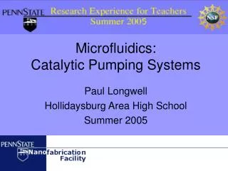
Microfluidics: Catalytic Pumping Systems. Paul Longwell Hollidaysburg Area High School Summer 2005. Catalytic?. http://www.mrsec.psu.edu/News/nugget3.html. Penn State researchers have built several nano-devices that move when place in a hydrogen peroxide solution.

E N D
Microfluidics: Catalytic Pumping Systems Paul Longwell Hollidaysburg Area High School Summer 2005
Catalytic? http://www.mrsec.psu.edu/News/nugget3.html Penn State researchers have built several nano-devices that move when place in a hydrogen peroxide solution. The platinum serves as a catalyst, helping the hydrogen peroxide decompose and produce oxygen gas bubbles. During this process, extra electrons are passed from the platinum to the gold and released into the solution. See movies of working nano-devices: http://research.chem.psu.edu/axsgroup/nanomov.htm
The Catalytic Pump Idea Using silver in place of gold, Penn State’s Jeffrey Catchmark designed the device (pictured) to see if a pumping effect could be produced. Based on flow patterns observed when testing previous devices, Dr. Catchmark believed the electrons would cause water molecules to be pulled alongside the conducting wire.
The RET Project As a participant of Penn State’s Research Experience for Teachers program, I worked under Dr. Catchmark to construct catalytic pumps using several different designs. These designs varied in the size and shape of the silver and gold plates as well as the thickness of the conducting wire.
The Fabrication Process • Building the catalytic pump involved the following steps: • Mapping out the structure of the devices. • Creating masks (patterns) to use in creating each component of the devices. • Applying the first-layer pattern on a silicon wafer. • Depositing/Lift-off of gold using first-layer pattern. • Applying the second-layer pattern over the first pattern. • Depositing/Lift-off of silver using second-layer pattern. • Applying a dielectric coating over the entire device. • Using the third-layer pattern to open “windows” to the silver/gold.
Creating the MasksThe Material After Dr. Catchmark designed the devices, the next step was to construct a template for each layer of material needed for the pumping device. The mask was made on a five-inch piece of soda-lime glass coated with chromium.
Creating the MasksWriting the Pattern Using a laser-writer, three separate masks were created. Each mask contained the pattern for one of the three layers of the pumping device. Here, the quartz square is loaded into the laser writer. The bottom of the writer.
Creating the MasksDeveloping the Pattern After being patterned by the laser writer, each mask must be developed using a Chromium Etch chemical. In this process, the chemical dissolves the chromium according to the pattern created by the laser.
1st Layer - GoldPhotolithography To begin building the pumping device, the pattern from the mask must be transferred onto a circular 3-inch silicon wafer.
1st Layer - GoldPhotolithography The LOR 1A is baked on before a second photoresist (SPR 3008) is applied and baked.
1st Layer - GoldPhotolithography Now coated with light-sensitive photoresist, the wafer is exposed to light through the first mask pattern.
1st Layer - GoldPhotolithography After one final bake, the exposed wafer is soaked in CD-26 developer and the photoresist is removed from the patterned areas.
1st Layer - GoldGold Deposition Using an electron-gun evaporator, the wafers are coated with 150 Angstroms of chrome and then 1000 Angstroms of gold.
1st Layer - GoldGold Lift-Off All gold outside of the patterned area is etched away with acetone and CD-26 developer.
2nd Layer - SilverPhotolithography As done previously with the first pattern, a layer of LOR1 and SPR-3008 photoresist are applied on top of the gold so that the silver features can be added.
2nd Layer - SilverAlignment For the device to function properly, it is extremely important that the new silver features matchup with the gold features as designed. Improper alignment results in defects in a device.
2nd Layer - SilverSilver Deposition This time silver is evaporated and deposited on the wafers.
2nd Layer - SilverSilver Lift-off Using acetone and CD-26 again, the silver is removed from everywhere except the patterned locations.
3rd Layer - DielectricFinal Layer To electrically insulate all of the components except for one gold window and one silver window, a layer of Spin-On Glass was applied on top of the wafer.
TestingIn Hydrogen Peroxide Solution For testing, devices were taken to the chemistry lab of Ph.D. student Tim Kline.
TestingIn Hydrogen Peroxide Solution The devices were tested in a 5% solution of hydrogen peroxide. Polystyrene microspheres and gold nanorods were used to assess the performance of the device.
Results The polystyrene spheres indicated no discernible flow pattern in the fluid surrounding the device. However…
Results The nanorods showed an attraction toward the silver metal even though the wire on this particular device was disconnected.
Conclusion The geometry of the pumping device seemed to be insignificant in affecting if/how the catalysis occurred. In fact, the reaction seemed to occur regardless of whether or not a direct connection was present between the silver and gold. (Assuming the amount of gold contained in the lead connected to the silver was significant to sustain the reaction.) Further research may reveal other factors (such as the substrate itself) that affect the nature of the reaction.
Thank You The staff at the Penn State Nanofabrication Facility were extremely helpful throughout this RET project. Jeff Catchmark, Operations Manager John McIntosh, Process Engineer Joseph Lonjin, Process Technician Guy Luvalee, Process Engineer Andrzej Mieckowski, Process Engineer Michael Rogosky, Process Engineer